全文地址:http://www.cnblogs.com/oomusou/articles/1270959.html
Abstract
TRDB-D5M是一個500萬像素的CMOS,可以搭配DE2或DE2-70做電腦視覺上的應用,不過很多人應該發現原廠的DE2_CAMERA_D5M範例,在VGA上delay嚴重,不像130萬像素的DE2_CCD範例那樣流暢。
Introduction
使用環境:Quartus II 7.2 SP3 + DE2 (Cyclone II EP2C35F672C6) + TRDB-D5M
會產生delay,主要在於曝光時間,若曝光時間越長,delay一定越嚴重,但曝光時間越短,亮度就越低,所以很難兩全。TRDB-D5M的register設定中,提供了對RGB gain的設定,也就是雖然曝光時間變短,但透過對RGB的補償,影像仍然不會太差。
I2C_CCD_Config.v / Verilog
1 module I2C_CCD_Config ( // Host Side
2 iCLK,
3 iRST_N,
4 iZOOM_MODE_SW,
5 iEXPOSURE_ADJ,
6 iEXPOSURE_DEC_p,
7 // I2C Side
8 I2C_SCLK,
9 I2C_SDAT
10 );
11
12 // Host Side
13 input iCLK;
14 input iRST_N;
15 input iZOOM_MODE_SW;
16
17 // I2C Side
18 output I2C_SCLK;
19 inout I2C_SDAT;
20
21 // Internal Registers/Wires
22 reg [15:0] mI2C_CLK_DIV;
23 reg [31:0] mI2C_DATA;
24 reg mI2C_CTRL_CLK;
25 reg mI2C_GO;
26 wire mI2C_END;
27 wire mI2C_ACK;
28 reg [23:0] LUT_DATA;
29 reg [5:0] LUT_INDEX;
30 reg [3:0] mSetup_ST;
31
32
33 ////////////// CMOS sensor registers setting //////////////////////
34
35 input iEXPOSURE_ADJ;
36 input iEXPOSURE_DEC_p;
37
38
39 parameter default_exposure = 16'h0438;
40 parameter exposure_change_value = 16'd50;
41
42 reg [24:0] combo_cnt;
43 wire combo_pulse;
44
45 reg [1:0] izoom_mode_sw_delay;
46
47 reg [3:0] iexposure_adj_delay;
48 wire exposure_adj_set;
49 wire exposure_adj_reset;
50 reg [15:0] senosr_exposure;
51
52 wire [23:0] sensor_start_row;
53 wire [23:0] sensor_start_column;
54 wire [23:0] sensor_row_size;
55 wire [23:0] sensor_column_size;
56 wire [23:0] sensor_row_mode;
57 wire [23:0] sensor_column_mode;
58
59 assign sensor_start_row = iZOOM_MODE_SW ? 24'h010036 : 24'h010000;
60 assign sensor_start_column = iZOOM_MODE_SW ? 24'h020010 : 24'h020000;
61 assign sensor_row_size = iZOOM_MODE_SW ? 24'h0303BF : 24'h03077F; //1920
62 assign sensor_column_size = iZOOM_MODE_SW ? 24'h0404FF : 24'h0409FF; //2560
63 assign sensor_row_mode = iZOOM_MODE_SW ? 24'h220000 : 24'h220011;
64 assign sensor_column_mode = iZOOM_MODE_SW ? 24'h230000 : 24'h230011;
65
66
67 always@(posedge iCLK or negedge iRST_N)
68 begin
69 if (!iRST_N)
70 begin
71 iexposure_adj_delay <= 0;
72 end
73 else
74 begin
75 iexposure_adj_delay <= {iexposure_adj_delay[2:0],iEXPOSURE_ADJ};
76 end
77 end
78
79 assign exposure_adj_set = ({iexposure_adj_delay[0],iEXPOSURE_ADJ}==2'b10) ? 1 : 0 ;
80 assign exposure_adj_reset = ({iexposure_adj_delay[3:2]}==2'b10) ? 1 : 0 ;
81
82 always@(posedge iCLK or negedge iRST_N)
83 begin
84 if (!iRST_N)
85 senosr_exposure <= default_exposure;
86 else if (exposure_adj_set|combo_pulse)
87 begin
88 if (iEXPOSURE_DEC_p)
89 begin
90 if ((senosr_exposure < exposure_change_value)||
91 (senosr_exposure == 16'h0))
92 senosr_exposure <= 0;
93 else
94 senosr_exposure <= senosr_exposure - exposure_change_value;
95 end
96 else
97 begin
98 if (((16'hffff -senosr_exposure) <exposure_change_value)||
99 (senosr_exposure == 16'hffff))
100 senosr_exposure <= 16'hffff;
101 else
102 senosr_exposure <= senosr_exposure + exposure_change_value;
103 end
104 end
105 end
106
107
108 always@(posedge iCLK or negedge iRST_N)
109 begin
110 if (!iRST_N)
111 combo_cnt <= 0;
112 else if (!iexposure_adj_delay[3])
113 combo_cnt <= combo_cnt + 1;
114 else
115 combo_cnt <= 0;
116 end
117
118 assign combo_pulse = (combo_cnt == 25'h1fffff) ? 1 : 0;
119
120 wire i2c_reset;
121
122 assign i2c_reset = iRST_N & ~exposure_adj_reset & ~combo_pulse ;
123
124 /////////////////////////////////////////////////////////////////////
125
126 // Clock Setting
127 parameter CLK_Freq = 50000000; // 50 MHz
128 parameter I2C_Freq = 20000; // 20 KHz
129 // LUT Data Number
130 parameter LUT_SIZE = 25;
131
132 ///////////////////// I2C Control Clock ////////////////////////
133 always@(posedge iCLK or negedge i2c_reset)
134 begin
135 if(!i2c_reset)
136 begin
137 mI2C_CTRL_CLK <= 0;
138 mI2C_CLK_DIV <= 0;
139 end
140 else
141 begin
142 if( mI2C_CLK_DIV < (CLK_Freq/I2C_Freq) )
143 mI2C_CLK_DIV <= mI2C_CLK_DIV+1;
144 else
145 begin
146 mI2C_CLK_DIV <= 0;
147 mI2C_CTRL_CLK <= ~mI2C_CTRL_CLK;
148 end
149 end
150 end
151 ////////////////////////////////////////////////////////////////////
152 I2C_Controller u0 ( .CLOCK(mI2C_CTRL_CLK), // Controller Work Clock
153 .I2C_SCLK(I2C_SCLK), // I2C CLOCK
154 .I2C_SDAT(I2C_SDAT), // I2C DATA
155 .I2C_DATA(mI2C_DATA), // DATA:[SLAVE_ADDR,SUB_ADDR,DATA]
156 .GO(mI2C_GO), // GO transfor
157 .END(mI2C_END), // END transfor
158 .ACK(mI2C_ACK), // ACK
159 .RESET(i2c_reset)
160 );
161 ////////////////////////////////////////////////////////////////////
162 ////////////////////// Config Control ////////////////////////////
163 //always@(posedge mI2C_CTRL_CLK or negedge iRST_N)
164 always@(posedge mI2C_CTRL_CLK or negedge i2c_reset)
165 begin
166 if(!i2c_reset)
167 begin
168 LUT_INDEX <= 0;
169 mSetup_ST <= 0;
170 mI2C_GO <= 0;
171
172 end
173
174 else if(LUT_INDEX<LUT_SIZE)
175 begin
176 case(mSetup_ST)
177 0: begin
178 mI2C_DATA <= {8'hBA,LUT_DATA};
179 mI2C_GO <= 1;
180 mSetup_ST <= 1;
181 end
182 1: begin
183 if(mI2C_END)
184 begin
185 if(!mI2C_ACK)
186 mSetup_ST <= 2;
187 else
188 mSetup_ST <= 0;
189 mI2C_GO <= 0;
190 end
191 end
192 2: begin
193 LUT_INDEX <= LUT_INDEX+1;
194 mSetup_ST <= 0;
195 end
196 endcase
197 end
198 end
199 ////////////////////////////////////////////////////////////////////
200 ///////////////////// Config Data LUT //////////////////////////
201 always
202 begin
203 case(LUT_INDEX)
204 0 : LUT_DATA <= 24'h000000;
205 1 : LUT_DATA <= 24'h20c000; // Mirror Row and Columns
206 2 : LUT_DATA <= {8'h09,senosr_exposure};// Exposure
207 3 : LUT_DATA <= 24'h050000; // H_Blanking
208 4 : LUT_DATA <= 24'h060019; // V_Blanking
209 5 : LUT_DATA <= 24'h0A8000; // change latch
210 6 : LUT_DATA <= 24'h2B0033; // Green 1 Gain
211 7 : LUT_DATA <= 24'h2C0135; // Blue Gain
212 8 : LUT_DATA <= 24'h2D0339; // Red Gain
213 9 : LUT_DATA <= 24'h2E0033; // Green 2 Gain
214 10 : LUT_DATA <= 24'h100051; // set up PLL power on
215 11 : LUT_DATA <= 24'h111807; // PLL_m_Factor<<8+PLL_n_Divider
216 12 : LUT_DATA <= 24'h120002; // PLL_p1_Divider
217 13 : LUT_DATA <= 24'h100053; // set USE PLL
218 14 : LUT_DATA <= 24'h980000; // disble calibration
219 15 : LUT_DATA <= 24'hA00000; // Test pattern control
220 16 : LUT_DATA <= 24'hA10000; // Test green pattern value
221 17 : LUT_DATA <= 24'hA20FFF; // Test red pattern value
222 18 : LUT_DATA <= sensor_start_row ; // set start row
223 19 : LUT_DATA <= sensor_start_column ; // set start column
224 20 : LUT_DATA <= sensor_row_size; // set row size
225 21 : LUT_DATA <= sensor_column_size; // set column size
226 22 : LUT_DATA <= sensor_row_mode; // set row mode in bin mode
227 23 : LUT_DATA <= sensor_column_mode; // set column mode in bin mode
228 24 : LUT_DATA <= 24'h4901A8; // row black target
229 default:LUT_DATA <= 24'h000000;
230 endcase
231 end
232
233 endmodule
39行
parameter default_exposure = 16'h0438;
將預設曝光值調小
210行
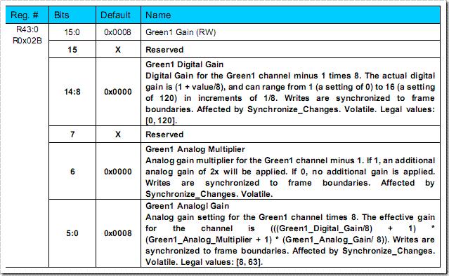
6 : LUT_DATA <= 24'h2B0033; // Green 1 Gain
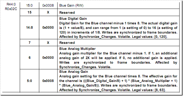
7 : LUT_DATA <= 24'h2C0135; // Blue Gain
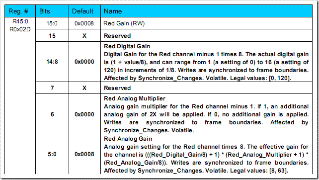
8 : LUT_DATA <= 24'h2D0339; // Red Gain
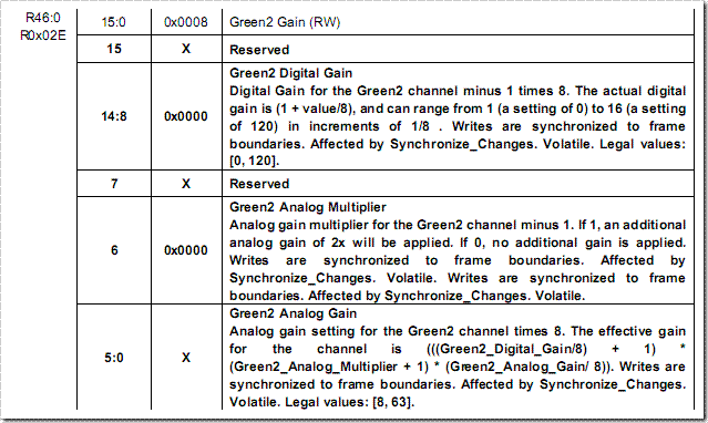
9 : LUT_DATA <= 24'h2E0033; // Green 2 Gain
7 : LUT_DATA <= 24'h2C0135; // Blue Gain
8 : LUT_DATA <= 24'h2D0339; // Red Gain
9 : LUT_DATA <= 24'h2E0033; // Green 2 Gain
設定RGB gain的register,根據CD內附的THDB-D5M_Hardware specification.pdf, 這幾個register的說明如下:


完整程式碼下載
DE2_CAMERA_D5M.7z (原廠範例)
DE2_CAMERA_D5M_fixed.7z (經過修改過的範例)
Conclusion
調整過曝光值與RGB gain後,delay的現象可以減少,但我目前還無法調到如130萬像素的DE2_CCD那樣流暢,所以在此拋磚引玉,希望有人能調出更好的結果。
Reference
THTB-D5M Terasic D5M Hardware specification