
The DSP’sEDMA is used to transfer data between memory and the TMS320DM642Video Port.
Tomaximize code reuse and streamline the integration process, bothdrivers are designed of two distinctive parts: the genericpart and the board specific part. The external devicecontrol interface (EDC) is defined to bind these two parts togetherin a plug-and-play manner.
The generic part of the drivers uses EDMAs totransfer data to and from the video ports.; The board-specific partmainly consists of code that in the case of the capture driver,initializes and configures the SAA7115 video decoder, and in thecase of the display driver, initializes and configures the SAA7105video encoder.These
EDC-compliant modules set up the video codecs towork together with the video ports to capture or display thedesired video data in a specific format. For example, the SAA7105can be configured to output video data in composite NTSC format orcomponent High-Definition 1080i format or a wide range of othervideo formats, depending on application requirements. In the meantime, the associated video port must also be configuredaccordingly.
The board-specific part also requires the EVM andthe DM642 DSP to be initialized by calling the EVM642_init()function from the DM642 EVM Board Support Library (BSL), whichcomes with the EVM. This will set up the EMIF, pin-muxconfigurations and the I2C controller. An application must link allthree libraries necessary in order to function correctly: one fromthe board-specific part, such as the SAA7115 or the SAA7105, onefrom the generic VPORTCAP or VPORTDIS part, and one from the BSL.These three libraries are called evm642_saa7115.l64, evm642_vportcap.l64, andevmdm642.l64, respectively for capture, and are calledevm642_saa7105.l64, evm642_vportdis.l64, and evmdm642.l64, respectively fordisplay.
2 Usage
2.1 Configuration
To use the capture or display device driver, adevice entry must be added and configured in the DSP/BIOSconfiguration tool.
The following are the device configurationsettings required to use the capture driver:
_ Init function: N/A, not used by this driver
_ Function table ptr: _VPORTCAP_Fxns
_ Function table type: IOM_Fxns
_ Device id: 0 or 1 for DM642 EVM:, specify which video port touse
_ Device params ptr: An optional pointer to an object of typeVPORT_PortParams as defined in the header file vport.h. Thispointer will point to a device parameter structure. Setting thispointer to NULL requires that an additional FVID_control call madefrom the application to initialize the video port. The parameterstructure is described below. An example of this structure is the _EVM642_vCapParamsNTSCPort that is defined intheevm642_vcapParamsNTSC.c file for NTSC format videocapture.
_ Device global data ptr: N/A, not used by this driver
The following are the device configurationsettings required to use the display driver:
_ Init function: N/A, not used by this driver
_ Function table ptr: _VPORTDIS_Fxns
_ Function table type: IOM_Fxns
_ Device id: 2 for DM642 EVM: specify which video port is inuse
_ Device params ptr: Same as for the capture driver
_ Device global data ptr: N/A, not used by this
2.2 Device Parameters for Generic Part of theDriver
通用视频端口部分的设备参数
2.2.1 Port Parameters (vport.h)
typedef struct VPORT_PortParams{
IntversionId; //Version number of the driver.
BooldualChanEnab; //Dual channel mode enable (captureonly).
Unsvc1Polarity; //polarity of the vctrl1 pin, either active high oractive low
Unsvc2Polarity; //polarity of the vctrl2 pin.
Unsvc3Polarity; //vctrl3 pin.
EDC_Fxns*edcTbl[2]; //array of up to two pointers of EDC functiontables, one for each channel. EDC函数表的两个指针数组
}VPORT_PortParams;
2.2.2Capture Channel Parameters (vportcap.h)
typedefstruct {Intcmode; // capture mode,
IntfldOp; // field and frame operation mode
Intscale; // horizontal ½ scaling enable
Intresmpl; // chroma horizontal 4:2:2 to 4:2:0 re-samplingenable
Int bpk10Bit; //10-bit packing mode,
InthCtRst; //horizontal counter reset mode.
IntvCtRst; // vertical counter reset
IntfldDect; // field detection enable, only used in external syncmode
IntextCtl; // external sync mode enable.
IntfldInv; // field inverse enable.
Uint16 fldXStrt1; // starting pixelnumber of field 1 ,≥0。
Uint16 fldYStrt1; //starting line number of field 1,≥1
Uint16fldXStrt2; //starting pixel number of field 2,≥0
Uint16fldYStrt2; //starting line number of field 2.≥1
Uint16 fldXStop1; //the last captured pixel of field one,≥ fldXStrt1
Uint16fldYStop1; //the last captured line of field one,≥ fldYStrt1
Uint16 fldXStop2;
Uint16 fldYStop2;
Uint16 thrld; //specifies number of double-words required togenerate DMA events
IntnumFrmBufs; //number of frame buffers to be allocated by driverto store video data captured
Intalignment; // memory alignment requirement for framebuffers
IntmergeFlds; // indicate whether to merge field one and two or tokeep them separate in memory.
Int segId; //DSP/BIOS memory segment ID, used by driver forframe buffer allocation
IntedmaPri; // priority level of EDMA transfers
IntirqId; // EDMA interrupt ID
}VPORTCAP_Params
The definitions of the bit-fields in the aboveparameter are mapped to the video port capture controlregister. The unnamed fields are there to represent thereserved bits in that register.
2.2.3Display Channel Parameters (vportdis.h)
typedef struct {
Intdmode; //display mode,
Int fldOp;
Intscale; //horizontal 2x scaling enable
Intresmpl;
Int defValEn; //default value output enable.
Int bpk10Bit;
Int vctl1Config; //VCTL1 pin output select.
Int vctl2Config;
Int vctl3Config;
IntextCtl; //external control enable
Uint16 frmHSize; //horizontal size of the video frame, including theblanking period视频帧的水平尺寸,包括消隐期
Uint16frmVSize; // 垂直尺寸。包括消隐期
Int16 imgHOffsetFld1;//display image horizontal offset in Field 1,relative to the end of horizontal blanking 显示图像在场1的水平偏移
Int16 imgVOffsetFld1; //在场1的垂直偏移
Uint16imgHSizeFld1; //显示图像在场1的像素宽度
Uint16imgVSizeFld1; //图像在场1的行高度
Int16 imgHOffsetFld2;
Int16 imgVOffsetFld2;
Uint16 imgHSizeFld2;
Uint16 imgVSizeFld2;
Uint16 hBlnkStart; //specifies the pixel number within the line onwhich horizontal blanking starts/stop.
Uint16hBlnkStop;
Uint16 vBlnkXStartFld1;//specifies the pixel number on which the verticalblanking starts for Field 1
Uint16 vBlnkYStartFld1;
Uint16 vBlnkXStopFld1;
Uint16 vBlnkYStopFld1;
Uint16 vBlnkXStartFld2;
Uint16 vBlnkYStartFld2;
Uint16 vBlnkXStopFld2;
Uint16 vBlnkYStopFld2;
Uint16 xStartFld1;
Uint16 yStartFld1;
Uint16 xStartFld2;
Uint16 yStartFld2;
Uint16 hSyncStart;
Uint16 hSyncStop;
Uint16 vSyncXStartFld1;
Uint16 vSyncYStartFld1;
Uint16 vSyncXStopFld1;
Uint16 vSyncYStopFld1;
Uint16 vSyncXStartFld2;
Uint16 vSyncYStartFld2;
Uint16 vSyncXStopFld2;
Uint16 vSyncYStopFld2;
Uint8 yClipLow;
Uint8 yClipHigh;
Uint8 cClipLow;
Uint8 cClipHigh;
Uint8 yDefVal;
Uint8 cbDefVal;
Uint8 crDefVal;
Int rgbX;
Int incPix;
Uint16 thrld;
Int numFrmBufs; //number of frame buffers to be allocated by driverto store video data captured
Int alignment;
Int mergeFlds;
Int segId;
Int edmaPri;
Int irqId;
}VPORTDIS_Params;
2.2.4 Video Port Global Interrupt Processing
typedef struct VPORT_VIntCbParams{
Int cbArg;
VPORT_IntCallBack vIntCbFxn;
Uint16 vIntMask;
Uint16 vIntLine;
Int irqId;
Uns intrMask;
} VPORT_VIntCbParams;
2.2.5Commands
The following are implemented run-time commandsdefined in vport.h:
VPORT_CMD_RESET: resets video port
VPORT_CMD_CONFIG_PORT: configures video port
VPORT_CMD_CONFIG_CHAN: configures a video channel
VPORT_CMD_START: starts capture or display operation
VPORT_CMD_STOP: stops capture or display operation
VPORT_CMD_SET_VINTCB: setup video port global interruptcall-back
VPORT_CMD_DUND_RECOVER: force video port to recover from displayunder-run
VPORT_CMD_COVR_RECOVER: force video port to recover from captureover-run
2.3 Device Parameters for Board Specific Part ofthe Drivers
特定编解码芯片驱动的设备参数
2.3.1 TheExternal Device Control (EDC) Interface
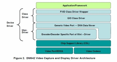
As showed in Figure 2, thecapture and display mini-drivers consist of the following twoparts:
•The generic part, which is designed to work as is withdifferent external video codecs and board layouts. All of itsdependencies lies within the DM642 device. For example, thevportdis.c file in the display mini-driver library, can be reusedwithout any code change with different video encoders on differentcustomer boards.
•The board specific part, whichonly works with specific video encoders or decoders on a specificboard. For example, the SAA7105.c file in the display mini-driverlibrary, only works with the Phillips SAA7105 video encoder on theDM642 EVM. Source code changes may be needed even if the sameencoder is used on a different board. The EDC interface is defined toallow seamless integration of these two parts in order to maximizecode reuse and minimize possible errors in the integration process.It defines a set of APIs that a board-specific part of themini-driver must implement in order to work with the genericpart.
#define EDC_CONFIG0x00000001
#define EDC_RESET0x00000002
#define EDC_START0x00000003
#define EDC_STOP0x00000004
#define EDC_GET_CONFIG0x00000005
#define EDC_GET_STATUS0x00000006
#define EDC_USER0x10000000
#define EDC_SUCCESS0
#define EDC_FAILED−1
typedef void*EDC_Handle;
typedef struct EDC_Fxns{
EDC_Handle(*open)(String name, Arg optArg);
Int (*close)(PtrdevHandle);
Int (*ctrl)(PtrdevHandle, Uns cmd, Arg arg);
} EDC_Fxns;
2.3.2 SAA7105Parameters
2.3.3 SAA7115Parameters
2.3.4 String NamingConvention in FVID_create()
3Architecture
3.1 BlockDiagram


3.2 Buffer Management
3.3 Cache Coherency
It is the application’s responsibility to ensurecache coherency, as the driver does nothing in this respect.This is because data istypically moved by EDMA between fast on-chip SRAM and slow off-chipSD-RAM for faster CPU access. Furthermore, algorithmscan use ping-pong buffer schemes to parallel the EDMA transfer andthe CPU execution, thus hiding most or all overhead associated withthe data movement. If this is the case, cache flush and cleanoperations can be avoided by aligning the frame buffers to cacheline boundaries.
However, if the application does access thesebuffers directly, the application must flush or clean the cache toensure cache coherency, the EDMA accesses external memory directlythrough the EMIF, while the CPU goes through the cache whenaccessing the data.
4 Constraints
This device driver does not support the followingmodes:
• Raw data capture
• Dual-channel synchronized raw-data display
• Synchronized to another video port
• Capture of MPEG transport stream