GpioPs in Depth – 3
GpioPs Driver API User Guide
Find the directory in Xilinx ISE installation ,we can find some useful driver api sources and documents, as shown following:

Go directly into gpiops_v1_01_a folder:

Driver sources locate in the src folder and documents locate in the doc folder. Besides, you can find some useful demo in examples folder, now let's take a drive!
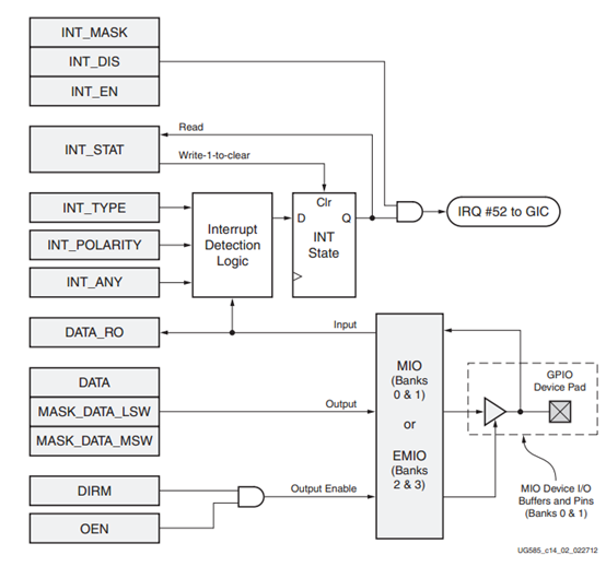
The is the most significant figure we want, by understand the fig above , we can grasp all the ways to use gpiops module:
DATA: Data register to write to ouput pin
MASK_DATA_LSW+MASK_DATA_MSW: another way to prevent read-modify-write time flow, write corresponding bit to 1 will set the specified pint , however the left 0 bit will keep unchanged, insteading of clear bit.
DRIM: Direction Register, 0 to disable the ouput.
OEN : 0 to disable output.
DATA_RO: pin value feed back, use as input data register.
INT_EN: interrupt enable
INT_DISABLE: interrupt disable
INT_MASK: interrupt enbable status register
INT_STAT: status of interrupt, write 1 to clear the pending interrupt.
INT_TYPE INT_POLARITY INT_ANY: interrupt type , such as level sensitive , edge sensitive
- Init functions:.
- XGpioPs_Config LookupConfig(DeviceID)
- Read and Write upt
- U32 Read(Bank)
- Void Write(Bank,Data)
- Int ReadPin(Pin)
- Void WritePin(Pin,Data)
- Set and Get Direction
- Void SetDirection(Bank,Direction)
- U32 GetDirection(Bank)
- Void SetDirectionPin(Pin,Direction)
- Int GetDirectionPin(Pin)
- Output Enable and Disable
- Void SetOutputEnable(Bank,Enable)
- U32 GetOutputEnable(Bank)
- Void SetOutputEnablePin(Pin,Enable)
- Int GetOutputEnablePin(Pin)
- Interrupt Enable and Disable, with Status feedback funcitons
- Void IntrEnable(Bank,Mask)
- Void IntrDisable(Bank,Mask)
- U32 IntrGetEnabled(Bank)
- Void IntrEnablePin(Pin)
- Void IntrDisablePin(Pin)
- IntrGetEnabledPin(Pin)
- Set and Get Interrupt type
- Void SetIntrType(Bank,IntrType,IntrPolarity,IntrOnAny)
- Void GetIntrType(Bank,IntrType,IntrPolarity,IntrOnAny)
- Void SetIntrTypePin(Bank,IrqType)
- U8 GetIntrTypePin(Pin)
- Interrupt Status and Clear interrupt
- U32 IntrGetStatus(Bank)
- Int IntrGetStatusPin(Pin)
- Void IntrClear(Bank,Mask)
- Void IntrClearPin(Pin)
- Interrupt Handler
- Void SetCallbackHandler(void* CallbackRef, XGpioPs_Handler FuncPtr)
- Void IntrHandler(*InstancePtr)
NOTICE:
I have ignore some exghausting details for the function name and definition, such as:
U32 Read(Bank) actually means:
U32 XGpioPs_Read(XGpioPs InstancePtr, U8 Bank)
As almost all the Xilinx Driver Libuary has a X and Module Name as the prefix, I ignore the prefix for a clear plot of the API. And the first parameters is a pointer to the Module Struct, I ignore it once again.
I think most of readers can understand the use for each function except the following 2 interrupt handler:
Void XGpioPs_SetCallbackHandler(XGpioPs* InstancePrt, void* CallbackRef, XGpioPs_Handler FuncPtr);
Void XGpioPs_IntrHandler(XGpioPs* InstancePtr);
ANNOUCEMENT:
As we know the function Read and Write will works on all the IO pins of a bank, and the function Read / Write Pin only Set one Pin a time. What if we a going to set the several Pins?
The usually Logic is to "read and modify then write". So you need to Read the register at first and then modify the specified bit on memory and write it to register at last.
We can offer a individual function such as :
SetOutput/Input(Mask)
In this way , if we use SetOutput, all the Mask bit are set Output, and the left keeps alone.