拓扑图

IP地址规划
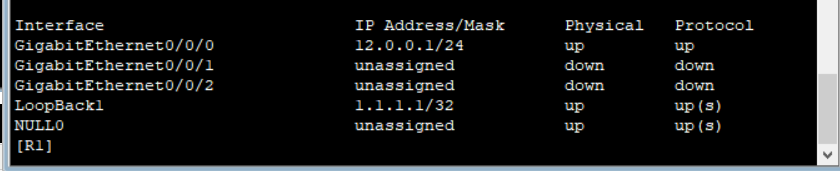
R1:利用OSPF跑通内网路由,再全局使能MPLS,接口激活MPLS,配置静态LSP
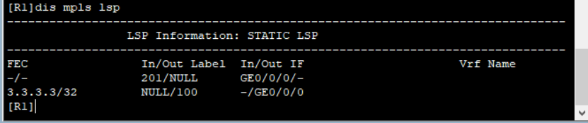
sy
sy R1
ospf 1
area 0
network 1.1.1.1 0.0.0.0
network 12.0.0.0 0.0.0.255
q
mpls lsr-id 1.1.1.1
mpls
q
int g0/0/0
mpls
q
static-lsp ingress to3 destination 3.3.3.3 255.255.255.255 nexthop 12.0.0.2 out-label100
static-lsp egress  to1 incoming-interface g0/0/0 in-label 201
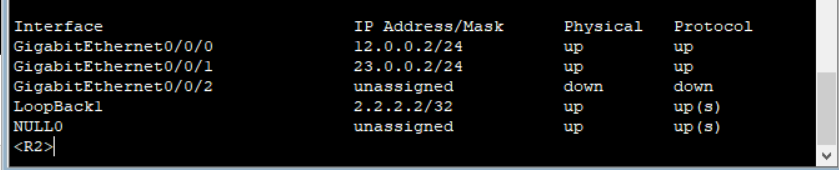
R2:同R1
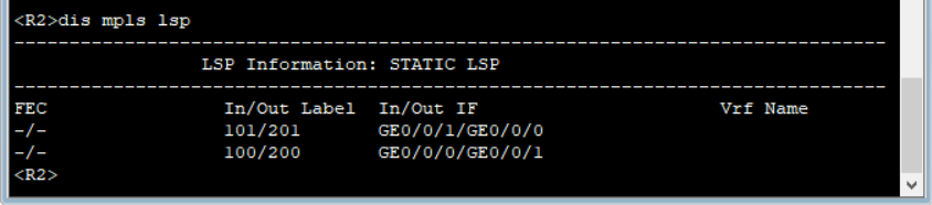
sy
sy R2
ospf 1
area 0
network 2.2.2.2 0.0.0.0
network 12.0.0.0 0.0.0.255
network 23.0.0.0 0.0.0.255
q
mpls lsr-id 2.2.2.2
mpls
q
int g0/0/0
mpls
int g0/0/1
mpls
q
static-lsp transit to3 incoming-interface GigabitEthernet0/0/0 in-label 100 nexthop 23.0.0.3 out-label 200
static-lsp transit to1 incoming-interface GigabitEthernet0/0/1 in-label 101 nexthop 12.0.0.1 out-label 201
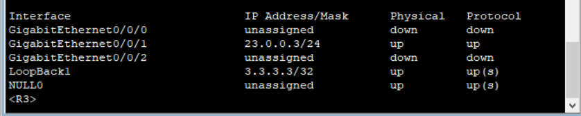
R3:同R1
sy
sy R3
ospf 1
area 0
network 3.3.3.3 0.0.0.0
network 23.0.0.0 0.0.0.255
q
mpls lsr-id 3.3.3.3
mpls
q
int g0/0/1
mpls
q
static-lsp egress to3 incoming-interface GigabitEthernet0/0/1 in-label 200
static-lsp ingress to1 destination 1.1.1.1 255.255.255.255 nexthop 23.0.0.2 out-label 101
查看mpls lsp

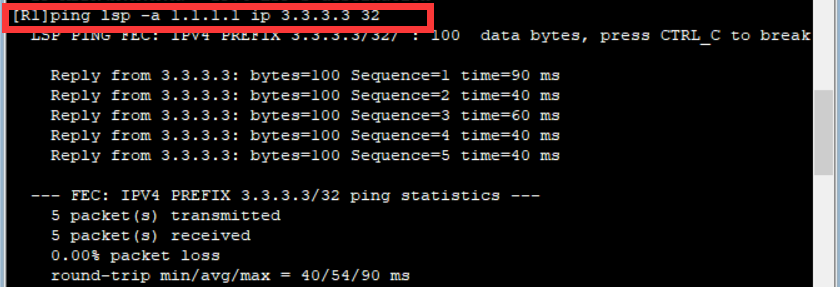
在R1上测试