在现有的项目上通过SoC的EHRPWM3B管脚产生PWM脉冲做为摄像头的framsync信号.
datasheet描述:
PWMSS:PWM Subsystem Resources
eHRPWM: Enhanced High Resolution Pulse Width Modulator 脉冲宽度调制器,产生pwm
eCAP: Enhanced Capture 增强型输入捕捉
eQEP: Enhanced Quadratured Pulse 增强的正弦波,只支持输入
eHRPWM:
- 专用的带有频率/周期控制的16位时基发生器
- 支持产生2组独立的PWM输出with Single edge operation
- 支持产生2组独立的PWM输出with Dual edge symmetric operation
- 支持产生1组独立的PWM输出with Dual edge symmetric operation
- Supports Dead-band generation with independent Rising and Falling edge delay control
- 在故障状态下, 提供PWM信号的异步越权控制
- Supports “trip zone” allocation of both latched and un-latched fault conditions
- CPU中断和ADC转换开始都允许触发事件
- Support PWM chopping by high frequency carrier signal, used for pulse transformer gate drives.
- 带有可编程延迟线的高分辨率模块
- 每个PWM周期可编程?Programmable on a per PWM period basis
- 可以在PWM脉冲的上升沿或者下降沿插入或者在两种边沿同时插入,亦或者两者都不插入Can be inserted either on the rising edge or falling edge of the PWM pulse or both or not at all
eCAP:
- 专用的输入捕捉管脚
- 32位时基发生器(counter)
- 4x32bit时间戳捕捉寄存器(PWMSS_ECAP_CAP1 - PWMSS_ECAP_CAP4)
- 4 stage sequencer (Mod4 counter) which is synchronized to external events (ECAPx pin edges)
- Independent Edge polarity (Rising/Falling edge) selection for all 4 events
- One-shot compare register (2 bits) to freeze captures after 1 to 4 Time-stamp events
- Control for continuous Time-stamp captures using a 4 deep circular buffer (PWMSS_ECAP_CAP1 -PWMSS_ECAP_CAP4) scheme
- Interrupt capabilities on any of the 4 capture events
eQEP:
- 输入同步
- Three Stage/Six Stage Digital Noise Filter
- 正弦波解码单元
- Position Counter and Control unit for position measurement
- Quadrature Edge Capture unit for low speed measurement
- Unit Time base for speed/frequency measurement
- Watchdog Timer for detecting stalls
对应的寄存器
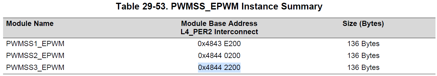
设备树描述
epwmss2: epwmss@48442000 {
	compatible = "ti,dra746-pwmss", "ti,am33xx-pwmss";
	reg = <0x48442000 0x30>;
	ti,hwmods = "epwmss2";
	#address-cells = <1>;
	#size-cells = <1>;
	status = "okay";
	ranges;

	ehrpwm2: pwm@48442200 {
		compatible = "ti,dra746-ehrpwm",
				 "ti,am3352-ehrpwm",
				 "ti,am33xx-ehrpwm";
		#pwm-cells = <3>;
		reg = <0x48442200 0x80>;
		clocks = <&ehrpwm2_tbclk>, <&l4_root_clk_div>;
		clock-names = "tbclk", "fck";
		status = "okay";
	};
...
};
通过调用以下脚本可以产生25Hz, duty=25%的pwm脉冲
#!/bin/sh
echo 1 > /sys/class/pwm/pwmchip0/export
# setup frequency to 25Hz duty cycle 25%
echo 40000000 > /sys/class/pwm/pwmchip0/pwm1/period
echo 10000000  > /sys/class/pwm/pwmchip0/pwm1/duty_cycle
echo normal > /sys/class/pwm/pwmchip0/pwm1/polarity
echo 1 > /sys/class/pwm/pwmchip0/pwm1/enable
echo "setting pwm for camera isp frame sync
代码流程:
系统上电初始化之后, 根据设备树注册一个名字为48442200.pwm的总线设备, 总线设备跟总线驱动匹配成功之后执行/driver/pwm/pwm-tiehrpwm.c的probe函数,
static int ehrpwm_pwm_probe(struct platform_device *pdev)
{
...
	ret = pwmchip_add(&pc->chip);
	if (ret < 0) {
		dev_err(&pdev->dev, "pwmchip_add() failed: %d
", ret);
		return ret;
	}
...
}
pwmchip_add函数定义在/driver/pwm/core.c里面
int pwmchip_add(struct pwm_chip *chip)
{
	return pwmchip_add_with_polarity(chip, PWM_POLARITY_NORMAL);
}
同样pwmchip_add_with_polarity函数也定义在core.c下
int pwmchip_add_with_polarity(struct pwm_chip *chip,
			      enum pwm_polarity polarity)
{
...
	pwmchip_sysfs_export(chip);
...
}
可在driver/pwm/sysfs.c下面找到pwmchip_sysfs_export的定义,这里调用了device_create在/sys/下面创建一个名字为pwmchip%d的目录.
void pwmchip_sysfs_export(struct pwm_chip *chip)
{
...
	parent = device_create(&pwm_class, chip->dev, MKDEV(0, 0), chip,
			       "pwmchip%d", chip->base);
...
}
并调用根据pwm_class定义的内核属性新建文件夹pwm
static struct class pwm_class = {
	.name = "pwm",
	.owner = THIS_MODULE,
	.dev_groups = pwm_chip_groups,
};
在pwm下面新建npwm, unexport, export三个文件
static ssize_t export_store(struct device *parent,
			    struct device_attribute *attr,
			    const char *buf, size_t len)
{
	struct pwm_chip *chip = dev_get_drvdata(parent);
	struct pwm_device *pwm;
	unsigned int hwpwm;
	int ret;

	ret = kstrtouint(buf, 0, &hwpwm);
	if (ret < 0)
		return ret;

	if (hwpwm >= chip->npwm)
		return -ENODEV;

	pwm = pwm_request_from_chip(chip, hwpwm, "sysfs");
	if (IS_ERR(pwm))
		return PTR_ERR(pwm);

	ret = pwm_export_child(parent, pwm);
	if (ret < 0)
		pwm_put(pwm);

	return ret ? : len;
}
static DEVICE_ATTR_WO(export);

static ssize_t unexport_store(struct device *parent,
			      struct device_attribute *attr,
			      const char *buf, size_t len)
{
	struct pwm_chip *chip = dev_get_drvdata(parent);
	unsigned int hwpwm;
	int ret;

	ret = kstrtouint(buf, 0, &hwpwm);
	if (ret < 0)
		return ret;

	if (hwpwm >= chip->npwm)
		return -ENODEV;

	ret = pwm_unexport_child(parent, &chip->pwms[hwpwm]);

	return ret ? : len;
}
static DEVICE_ATTR_WO(unexport);

static ssize_t npwm_show(struct device *parent, struct device_attribute *attr,
			 char *buf)
{
	const struct pwm_chip *chip = dev_get_drvdata(parent);

	return sprintf(buf, "%u
", chip->npwm);
}
static DEVICE_ATTR_RO(npwm);

static struct attribute *pwm_chip_attrs[] = {
	&dev_attr_export.attr,
	&dev_attr_unexport.attr,
	&dev_attr_npwm.attr,
	NULL,
};
ATTRIBUTE_GROUPS(pwm_chip);
往生成的export里面写数据才会生成新的目录
static ssize_t export_store(struct device *parent,
			    struct device_attribute *attr,
			    const char *buf, size_t len)
{
...
	ret = pwm_export_child(parent, pwm);
...
}
如下在调用export之后先生成一个pwm%d的目录
static int pwm_export_child(struct device *parent, struct pwm_device *pwm)
{
...
	export->child.release = pwm_export_release;
	export->child.parent = parent;
	export->child.devt = MKDEV(0, 0);
	export->child.groups = pwm_groups;
	dev_set_name(&export->child, "pwm%u", pwm->hwpwm);
...
}
上面函数调用了pwm_groups,而pwm_groups定义如下
static DEVICE_ATTR_RW(period);
static DEVICE_ATTR_RW(duty_cycle);
static DEVICE_ATTR_RW(enable);
static DEVICE_ATTR_RW(polarity);

static struct attribute *pwm_attrs[] = {
	&dev_attr_period.attr,
	&dev_attr_duty_cycle.attr,
	&dev_attr_enable.attr,
	&dev_attr_polarity.attr,
	NULL
};
脚本里先往export里面写1,然后才能在生成新的文件之后做其他操作.
