4412的板子IO都是1.8v的。只有I2C6是用了电平转换到了3.3v。所以我准备使用I2C6来驱动mpu9250
一、首先去掉占用的模块
menuconfig中去掉触摸的驱动
- Device Drivers --->
- Input device support --->
- Touchscreens --->
- FT5X0X based touchscreens(去掉)
然后是去掉RC522的驱动(SPI占用I2C了)
- Device Drivers --->
- SPI support --->
- < > RC522 Module driver support(去掉)
-> Networking support (NET [=y])
-> CAN bus subsystem support (CAN [=y])
-> CAN Device Drivers
-> Platform CAN drivers with Netlink support (CAN_DEV [=y])
< > Microchip MCP251x SPI CAN controllers
二、在mach-itop4412.c中添加设备
static struct i2c_board_info i2c_devs6[] __initdata = {
    {
        I2C_BOARD_INFO("mpu9250", MPU9250_ADDRESS),
    },
};
这里的MPU9250_ADDRESS应该是7位的,如果写0XD0,就是MPU9250_ADDRESS>>1
然后内核编译后,烧录进开发板
cat /sys/bus/i2c/devices下就会有6-0068,这个文件了
写了一个空的I2C模版:


#include <linux/kernel.h>
#include <linux/module.h>
#include <linux/i2c.h>
#include <linux/input.h>
#include <linux/delay.h>
#include <linux/slab.h>
#include <linux/interrupt.h>
#include <linux/irq.h>
#include <linux/gpio.h>
#include <linux/platform_device.h>

#include <linux/regulator/consumer.h>

#include <mach/gpio.h>
#include <plat/gpio-cfg.h>
#include <plat/ft5x0x_touch.h>

#define I2C6_9250_NAME "mpu9250"

#define I2C_SDA6    EXYNOS4_GPC1(3)
#define I2C_SCL6    EXYNOS4_GPC1(4)

static int i2c_mpu9250_probe(struct i2c_client *client, const struct i2c_device_id *id)
{
    printk("==%s:
", __FUNCTION__);
    return 0;
}

static int __devexit i2c_mpu9250_remove(struct i2c_client *client)
{
    i2c_set_clientdata(client, NULL);               //设置client为NULL
    printk("==%s:
", __FUNCTION__);
    return 0;
}

static const struct i2c_device_id i2c_mpu9250_id[] = {
    { I2C6_9250_NAME, 0 },
    { }
};

static struct i2c_driver i2c_mpu9250_driver = {
    .probe = i2c_mpu9250_probe,
    .remove = __devexit_p(i2c_mpu9250_remove),
    .id_table = i2c_mpu9250_id,
    .driver = {
        .name  = I2C6_9250_NAME,
        .owner = THIS_MODULE,
    },
};

static void i2c_io_init()
{
    int ret;
    ret = gpio_request(I2C_SCL6, "I2C_SCL6");
    if(ret) {
        printk(KERN_ERR "failed to request TP1_EN for I2C control
");
    }

    gpio_direction_output(I2C_SCL6, 1);
    s3c_gpio_cfgpin(I2C_SCL6, S3C_GPIO_OUTPUT);
    gpio_free(I2C_SCL6);

    mdelay(5);

    ret = gpio_request(I2C_SDA6, "I2C_SDA6");
    if(ret) {
        gpio_free(I2C_SDA6);

        ret = gpio_request(I2C_SDA6, "I2C_SDA6");
        if(ret) {
            printk("i2c_io_test: Fialed to request I2C_SDA6
");
        }
    }
    gpio_direction_output(I2C_SDA6, 0);
    mdelay(200);

    gpio_direction_output(I2C_SDA6, 1);

    s3c_gpio_cfgpin(I2C_SDA6, S3C_GPIO_OUTPUT);
    gpio_free(I2C_SDA6);
    msleep(300);
    printk("==%s:
", __FUNCTION__);
}

static int __init i2c_mpu9250_init(void)
{
    printk("==%s:
", __FUNCTION__);
    i2c_io_init();
    return i2c_add_driver(&i2c_mpu9250_driver);
}

static void __exit i2c_mpu9250_exit(void)
{
    printk("==%s:
", __FUNCTION__);
    i2c_del_driver(&i2c_mpu9250_driver);
}

late_initcall(i2c_mpu9250_init);       //延迟加载
module_exit(i2c_mpu9250_exit);

MODULE_LICENSE("GPL");
MODULE_DESCRIPTION("mpu9250");
MODULE_AUTHOR("ChenTuo");
三、I2C架构层次分类
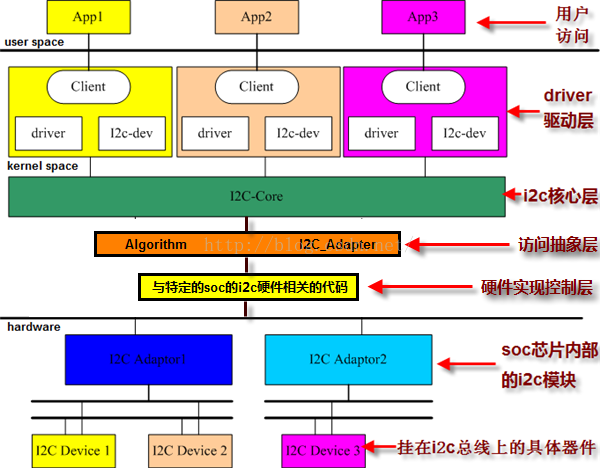
- 第一层:提供i2c adapter的硬件驱动,探测、初始化i2c adapter(如申请i2c的io地址和中断号),驱动soc控制的i2c adapter在硬件上产生信号(start、stop、ack)以及处理i2c中断。覆盖图中的硬件实现层
- 第二层:提供i2c adapter的algorithm,用具体适配器的xxx_xferf()函数来填充i2c_algorithm的master_xfer函数指针,并把赋值后的i2c_algorithm再赋值给i2c_adapter的algo指针。覆盖图中的访问抽象层、i2c核心层
- 第三层:实现i2c设备驱动中的i2c_driver接口,用具体的i2c device设备的attach_adapter()、detach_adapter()方法赋值给i2c_driver的成员函数指针。实现设备device与总线(或者叫adapter)的挂接。覆盖图中的driver驱动层
- 第四层:实现i2c设备所对应的具体device的驱动,i2c_driver只是实现设备与总线的挂接,而挂接在总线上的设备则是千差万别的,所以要实现具体设备device的write()、read()、ioctl()等方法,赋值给file_operations,然后注册字符设备(多数是字符设备)。覆盖图中的driver驱动层。
- --------------------- 本文来自 zqixiao_09 的CSDN 博客 ,全文地址请点击:https://blog.csdn.net/zqixiao_09/article/details/50916916?utm_source=copy
四、Linux下I2C驱动体系结构三部分详细分析
4.1 IIC核心
IIC核心提供了IIC总线驱动和设别驱动的注册、注销方法。在LInux驱动的I2C文件夹下有alogs,busses,chips三个文件夹,另外还有i2c-core.c和i2c-dev.c两个文件。
4.2 IIC总线驱动
IIC总线驱动是对IIC硬件的,适配器可由CPU控制,IIC直接集成在CPU内部。IIC驱动包括IIC适配器数据结构体i2c_adapter、IIC适配器的algorithm数据结构i2c-algorithm和控制器产生通信信号的函数。i2c_algorithm里有iic_xfer就是i2c的低层读写实现。
4.3 IIC设备驱动
IIC设备驱动主要包含了数据结构i2c_driver和i2c_client,我们需要根据具体设备实现其中的成员函数。
i2c-dev.c文件中实现了I2Cdriver,包括实现open,release,read,write以及ioctl等标准文件操作的接口函数。
通过I2Cdriver提供的通用方法可以访问任何一个I2C设备。
五、一些相关的数据结构
i2c_msg:
struct i2c_msg {
    __u16 addr;    /* slave address            */
    __u16 flags;
#define I2C_M_TEN        0x0010    /* this is a ten bit chip address */
#define I2C_M_RD        0x0001    /* read data, from slave to master */
#define I2C_M_NOSTART        0x4000    /* if I2C_FUNC_PROTOCOL_MANGLING */
#define I2C_M_REV_DIR_ADDR    0x2000    /* if I2C_FUNC_PROTOCOL_MANGLING */
#define I2C_M_IGNORE_NAK    0x1000    /* if I2C_FUNC_PROTOCOL_MANGLING */
#define I2C_M_NO_RD_ACK        0x0800    /* if I2C_FUNC_PROTOCOL_MANGLING */
#define I2C_M_RECV_LEN        0x0400    /* length will be first received byte */
    __u16 len;        /* msg length                */
    __u8 *buf;        /* pointer to msg data            */
};
I2C_M_TEN:I2C默认就是8位的,如果i2c_msg的flags没有配置I2C_M_TEN的话
I2C_M_RD:标识这是一个读操作
I2C_M_NOSTART:没有起始位
I2C_M_REV_DIR_ADDR:读写标识位反转
I2C_M_IGNORE_NAK:忽略ACK和NACK
I2C_M_NO_RD_ACK:读时忽略ACK