[译]Vulkan教程(32)生成mipmap
Generating Mipmaps 生成mipmap
Introduction 入门
Our program can now load and render 3D models. In this chapter, we will add one more feature, mipmap generation. Mipmaps are widely used in games and rendering software, and Vulkan gives us complete control over how they are created.
现在我们的程序可以加载和渲染3D模型了。本章,我们将添加一个特性,mipmap生成。Mipmap广泛应用于游戏和渲染软件,Vulkan给了我们完全的控制权-关于如何创建它们。
Mipmaps are precalculated, downscaled versions of an image. Each new image is half the width and height of the previous one. Mipmaps are used as a form of Level of Detail or LOD. Objects that are far away from the camera will sample their textures from the smaller mip images. Using smaller images increases the rendering speed and avoids artifacts such as Moiré patterns. An example of what mipmaps look like:
Mipmap是预计算的,缩小版本的image。每个新image都是是一个的宽度和高度的一半。Mipmap用于作为Level of Detail(即LOD)的一种方式。远离摄像机的对象会从纹理的比较小的mip图像上采样。使用更小的image会增加渲染速度,避免Moiré patterns这样的锯齿。一个mipmap的例子如下:
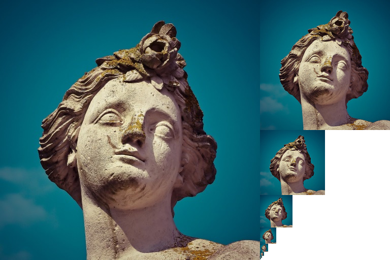
Image creation
In Vulkan, each of the mip images is stored in different mip levels of a VkImage. Mip level 0 is the original image, and the mip levels after level 0 are commonly referred to as the mip chain.
在Vulkan中,每个mip图像都保存在VkImage的不同的mip层里。Mip层0是最初的图像,之后的mip层被称为mip链。
The number of mip levels is specified when the VkImage is created. Up until now, we have always set this value to one. We need to calculate the number of mip levels from the dimensions of the image. First, add a class member to store this number:
Mip层的数量在VkImage 创建时指定。直到现在,我们总数设置这个值为1。我们需要根据image的维度计算mip层的数量。首先,添加类成员to记录这个数:
...
uint32_t mipLevels;
VkImage textureImage;
...
The value for mipLevels can be found once we've loaded the texture in createTextureImage:
mipLevels 的值可以在我们在createTextureImage加载了纹理之后立即得到:
int texWidth, texHeight, texChannels;
stbi_uc* pixels = stbi_load(TEXTURE_PATH.c_str(), &texWidth, &texHeight, &texChannels, STBI_rgb_alpha);
...
mipLevels = static_cast<uint32_t>(std::floor(std::log2(std::max(texWidth, texHeight)))) + 1;
This calculates the number of levels in the mip chain. The max function selects the largest dimension. The log2 function calculates how many times that dimension can be divided by 2. The floor function handles cases where the largest dimension is not a power of 2. 1 is added so that the original image has a mip level.
这计算了mip链中的层的数量。max 函数选择了最大的维度。log2函数计算维度可以被2除多少次。floor 函数处理最大维度不是2的指数的问题。增加1使得原始图像有1个mip层。
To use this value, we need to change the createImage, createImageView, and transitionImageLayout functions to allow us to specify the number of mip levels. Add a mipLevels parameter to the functions:
为使用这个值,我们需要修改createImage、createImageView和transitionImageLayout 函数to允许我们指定mip层的数量。给这些函数添加mipLevels 参数:
void createImage(uint32_t width, uint32_t height, uint32_t mipLevels, VkFormat format, VkImageTiling tiling, VkImageUsageFlags usage, VkMemoryPropertyFlags properties, VkImage& image, VkDeviceMemory& imageMemory) {
    ...
    imageInfo.mipLevels = mipLevels;
    ...
}
VkImageView createImageView(VkImage image, VkFormat format, VkImageAspectFlags aspectFlags, uint32_t mipLevels) {
    ...
    viewInfo.subresourceRange.levelCount = mipLevels;
    ...
void transitionImageLayout(VkImage image, VkFormat format, VkImageLayout oldLayout, VkImageLayout newLayout, uint32_t mipLevels) {
    ...
    barrier.subresourceRange.levelCount = mipLevels;
    ...
Update all calls to these functions to use the right values:
更新所有对这些函数的调用,使用正确的值:
createImage(swapChainExtent.width, swapChainExtent.height, 1, depthFormat, VK_IMAGE_TILING_OPTIMAL, VK_IMAGE_USAGE_DEPTH_STENCIL_ATTACHMENT_BIT, VK_MEMORY_PROPERTY_DEVICE_LOCAL_BIT, depthImage, depthImageMemory);
...
createImage(texWidth, texHeight, mipLevels, VK_FORMAT_R8G8B8A8_UNORM, VK_IMAGE_TILING_OPTIMAL, VK_IMAGE_USAGE_TRANSFER_DST_BIT | VK_IMAGE_USAGE_SAMPLED_BIT, VK_MEMORY_PROPERTY_DEVICE_LOCAL_BIT, textureImage, textureImageMemory);
swapChainImageViews[i] = createImageView(swapChainImages[i], swapChainImageFormat, VK_IMAGE_ASPECT_COLOR_BIT, 1);
...
depthImageView = createImageView(depthImage, depthFormat, VK_IMAGE_ASPECT_DEPTH_BIT, 1);
...
textureImageView = createImageView(textureImage, VK_FORMAT_R8G8B8A8_UNORM, VK_IMAGE_ASPECT_COLOR_BIT, mipLevels);
transitionImageLayout(depthImage, depthFormat, VK_IMAGE_LAYOUT_UNDEFINED, VK_IMAGE_LAYOUT_DEPTH_STENCIL_ATTACHMENT_OPTIMAL, 1);
...
transitionImageLayout(textureImage, VK_FORMAT_R8G8B8A8_UNORM, VK_IMAGE_LAYOUT_UNDEFINED, VK_IMAGE_LAYOUT_TRANSFER_DST_OPTIMAL, mipLevels);
Generating Mipmaps 生成mipmap
Our texture image now has multiple mip levels, but the staging buffer can only be used to fill mip level 0. The other levels are still undefined. To fill these levels we need to generate the data from the single level that we have. We will use the vkCmdBlitImage command. This command performs copying, scaling, and filtering operations. We will call this multiple times to blit data to each level of our texture image.
我们的纹理图像现在有多个mip层,但是暂存buffer只能用于填充mp层0。其他的层还是未定义的。问填入这些层,我们需要为每个层生成数据。我们要用vkCmdBlitImage 命令。这个命令试试复制、缩放和过滤操作。我们多次调用它来位块传送blit数据到每个层。
VkCmdBlit is considered a transfer operation, so we must inform Vulkan that we intend to use the texture image as both the source and destination of a transfer. Add VK_IMAGE_USAGE_TRANSFER_SRC_BIT to the texture image's usage flags in createTextureImage:
VkCmdBlit 被认为是转移操作,所以我们必须通知Vulkan,我们想使用纹理图像既作为源又作为目标。在createTextureImage中添加VK_IMAGE_USAGE_TRANSFER_SRC_BIT 到纹理图像的用法标志:
...
createImage(texWidth, texHeight, mipLevels, VK_FORMAT_R8G8B8A8_UNORM, VK_IMAGE_TILING_OPTIMAL, VK_IMAGE_USAGE_TRANSFER_SRC_BIT | VK_IMAGE_USAGE_TRANSFER_DST_BIT | VK_IMAGE_USAGE_SAMPLED_BIT, VK_MEMORY_PROPERTY_DEVICE_LOCAL_BIT, textureImage, textureImageMemory);
...
Like other image operations, vkCmdBlitImage depends on the layout of the image it operates on. We could transition the entire image to VK_IMAGE_LAYOUT_GENERAL, but this will most likely be slow. For optimal performance, the source image should be in VK_IMAGE_LAYOUT_TRANSFER_SRC_OPTIMAL and the destination image should be in VK_IMAGE_LAYOUT_TRANSFER_DST_OPTIMAL. Vulkan allows us to transition each mip level of an image independently. Each blit will only deal with two mip levels at a time, so we can transition each level into the optimal layout between blits commands.
像其他图像操作一样,vkCmdBlitImage 依赖于image的布局。我们可以转换整个image到VK_IMAGE_LAYOUT_GENERAL,但是这会很慢。为最优性能考虑,源image应当是VK_IMAGE_LAYOUT_TRANSFER_SRC_OPTIMAL ,目标image应当是VK_IMAGE_LAYOUT_TRANSFER_DST_OPTIMAL。Vulkan允许我们独立地转换每个mip层。每次blit只会处理2个mip层,所以我们可以在两次blit命令之间转换每个层到最优布局。
transitionImageLayout only performs layout transitions on the entire image, so we'll need to write a few more pipeline barrier commands. Remove the existing transition to VK_IMAGE_LAYOUT_SHADER_READ_ONLY_OPTIMAL in createTextureImage:
transitionImageLayout 只在整个image上实施布局转换,所以我们需要再写点管道屏障命令。将createTextureImage中已有的转换改为VK_IMAGE_LAYOUT_SHADER_READ_ONLY_OPTIMAL :
...
transitionImageLayout(textureImage, VK_FORMAT_R8G8B8A8_UNORM, VK_IMAGE_LAYOUT_UNDEFINED, VK_IMAGE_LAYOUT_TRANSFER_DST_OPTIMAL, mipLevels);
    copyBufferToImage(stagingBuffer, textureImage, static_cast<uint32_t>(texWidth), static_cast<uint32_t>(texHeight));
//transitioned to VK_IMAGE_LAYOUT_SHADER_READ_ONLY_OPTIMAL while generating mipmaps
...
This will leave each level of the texture image in VK_IMAGE_LAYOUT_TRANSFER_DST_OPTIMAL. Each level will be transitioned to VK_IMAGE_LAYOUT_SHADER_READ_ONLY_OPTIMAL after the blit command reading from it is finished.
这会让各个层处于VK_IMAGE_LAYOUT_TRANSFER_DST_OPTIMAL。在blit命令从层读取完成后,每个层会被转换为VK_IMAGE_LAYOUT_SHADER_READ_ONLY_OPTIMAL 。
We're now going to write the function that generates the mipmaps:
我们现在要写这个函数that生成mipmap:
void generateMipmaps(VkImage image, int32_t texWidth, int32_t texHeight, uint32_t mipLevels) {
    VkCommandBuffer commandBuffer = beginSingleTimeCommands();

    VkImageMemoryBarrier barrier = {};
    barrier.sType = VK_STRUCTURE_TYPE_IMAGE_MEMORY_BARRIER;
    barrier.image = image;
    barrier.srcQueueFamilyIndex = VK_QUEUE_FAMILY_IGNORED;
    barrier.dstQueueFamilyIndex = VK_QUEUE_FAMILY_IGNORED;
    barrier.subresourceRange.aspectMask = VK_IMAGE_ASPECT_COLOR_BIT;
    barrier.subresourceRange.baseArrayLayer = 0;
    barrier.subresourceRange.layerCount = 1;
    barrier.subresourceRange.levelCount = 1;

    endSingleTimeCommands(commandBuffer);
}
We're going to make several transitions, so we'll reuse this VkImageMemoryBarrier. The fields set above will remain the same for all barriers. subresourceRange.miplevel, oldLayout, newLayout, srcAccessMask, and dstAccessMask will be changed for each transition.
我们要做几个转换,所以我们复用这个VkImageMemoryBarrier。上述字段的设置会对所有的屏障想通subresourceRange.miplevel、oldLayout、newLayout、srcAccessMask和dstAccessMask 会随着每个转换而改变。
int32_t mipWidth = texWidth;
int32_t mipHeight = texHeight;

for (uint32_t i = 1; i < mipLevels; i++) {

}
This loop will record each of the VkCmdBlitImage commands. Note that the loop variable starts at 1, not 0.
这个循环会录制每个VkCmdBlitImage 命令。注意,循环变量从1开始,不是0。
barrier.subresourceRange.baseMipLevel = i - 1;
barrier.oldLayout = VK_IMAGE_LAYOUT_TRANSFER_DST_OPTIMAL;
barrier.newLayout = VK_IMAGE_LAYOUT_TRANSFER_SRC_OPTIMAL;
barrier.srcAccessMask = VK_ACCESS_TRANSFER_WRITE_BIT;
barrier.dstAccessMask = VK_ACCESS_TRANSFER_READ_BIT;

vkCmdPipelineBarrier(commandBuffer,
    VK_PIPELINE_STAGE_TRANSFER_BIT, VK_PIPELINE_STAGE_TRANSFER_BIT, 0,
    0, nullptr,
    0, nullptr,
    1, &barrier);
First, we transition level i - 1 to VK_IMAGE_LAYOUT_TRANSFER_SRC_OPTIMAL. This transition will wait for level i - 1 to be filled, either from the previous blit command, or from vkCmdCopyBufferToImage. The current blit command will wait on this transition.
首先,我们转换层i - 1到VK_IMAGE_LAYOUT_TRANSFER_SRC_OPTIMAL。这个转换会等待层i - 1被填入,或者来自上一个blit命令,或者来自vkCmdCopyBufferToImage。当前blit命令会等待这次转换。
VkImageBlit blit = {};
blit.srcOffsets[0] = { 0, 0, 0 };
blit.srcOffsets[1] = { mipWidth, mipHeight, 1 };
blit.srcSubresource.aspectMask = VK_IMAGE_ASPECT_COLOR_BIT;
blit.srcSubresource.mipLevel = i - 1;
blit.srcSubresource.baseArrayLayer = 0;
blit.srcSubresource.layerCount = 1;
blit.dstOffsets[0] = { 0, 0, 0 };
blit.dstOffsets[1] = { mipWidth > 1 ? mipWidth / 2 : 1, mipHeight > 1 ? mipHeight / 2 : 1, 1 };
blit.dstSubresource.aspectMask = VK_IMAGE_ASPECT_COLOR_BIT;
blit.dstSubresource.mipLevel = i;
blit.dstSubresource.baseArrayLayer = 0;
blit.dstSubresource.layerCount = 1;
Next, we specify the regions that will be used in the blit operation. The source mip level is i - 1 and the destination mip level is i. The two elements of the srcOffsets array determine the 3D region that data will be blitted from. dstOffsets determines the region that data will be blitted to. The X and Y dimensions of the dstOffsets[1] are divided by two since each mip level is half the size of the previous level. The Z dimension of srcOffsets[1] and dstOffsets[1] must be 1, since a 2D image has a depth of 1.
接下来,我们知道要被这次blit操作使用的区域。源mip层是i - 1,目标mip层是i。srcOffsets 数组的2个元素决定了数据会从哪个区域填充。dstOffsets 决定了数据会被填入的区域。dstOffsets[1] 的X和Y维度被2除,因为每个mip层都是上一个的一半。srcOffsets[1] 和dstOffsets[1]的Z维度必须是1,因为2D图像的深度就是1。
vkCmdBlitImage(commandBuffer,
    image, VK_IMAGE_LAYOUT_TRANSFER_SRC_OPTIMAL,
    image, VK_IMAGE_LAYOUT_TRANSFER_DST_OPTIMAL,
    1, &blit,
    VK_FILTER_LINEAR);
Now, we record the blit command. Note that textureImage is used for both the srcImage and dstImage parameter. This is because we're blitting between different levels of the same image. The source mip level was just transitioned to VK_IMAGE_LAYOUT_TRANSFER_SRC_OPTIMAL and the destination level is still in VK_IMAGE_LAYOUT_TRANSFER_DST_OPTIMAL from createTextureImage.
现在,我们录制blit命令。注意,textureImage 同时用于srcImage 和dstImage参数。这是因为我们要在同一图像的不同层上blit。源mip层被转换为VK_IMAGE_LAYOUT_TRANSFER_SRC_OPTIMAL ,目标mip层还是从createTextureImage来的VK_IMAGE_LAYOUT_TRANSFER_DST_OPTIMAL 。
The last parameter allows us to specify a VkFilter to use in the blit. We have the same filtering options here that we had when making the VkSampler. We use the VK_FILTER_LINEAR to enable interpolation.
最后一个参数允许我们指定用于blit的VkFilter 。我们制作时也使用了相同的过滤选项。我们使用VK_FILTER_LINEAR 来启用插值。
barrier.oldLayout = VK_IMAGE_LAYOUT_TRANSFER_SRC_OPTIMAL;
barrier.newLayout = VK_IMAGE_LAYOUT_SHADER_READ_ONLY_OPTIMAL;
barrier.srcAccessMask = VK_ACCESS_TRANSFER_READ_BIT;
barrier.dstAccessMask = VK_ACCESS_SHADER_READ_BIT;

vkCmdPipelineBarrier(commandBuffer,
    VK_PIPELINE_STAGE_TRANSFER_BIT, VK_PIPELINE_STAGE_FRAGMENT_SHADER_BIT, 0,
    0, nullptr,
    0, nullptr,
    1, &barrier);
This barrier transitions mip level i - 1 to VK_IMAGE_LAYOUT_SHADER_READ_ONLY_OPTIMAL. This transition waits on the current blit command to finish. All sampling operations will wait on this transition to finish.
这个屏障转换mip层i - 1为VK_IMAGE_LAYOUT_SHADER_READ_ONLY_OPTIMAL。这个转换等待当前blit命令完成。所有的采样操作都会等待这个转换完成。
    ...
    if (mipWidth > 1) mipWidth /= 2;
    if (mipHeight > 1) mipHeight /= 2;
}
At the end of the loop, we divide the current mip dimensions by two. We check each dimension before the division to ensure that dimension never becomes 0. This handles cases where the image is not square, since one of the mip dimensions would reach 1 before the other dimension. When this happens, that dimension should remain 1 for all remaining levels.
在循环的结尾,我们将当前mip维度除以2。我们检查每个维度before除法,以确保维度不会成为0。这处理了image不是正方形的情况,因为其中一个mip维度会先到达1。此时,那个维度就应当继续为1 for剩下的层。
    barrier.subresourceRange.baseMipLevel = mipLevels - 1;
    barrier.oldLayout = VK_IMAGE_LAYOUT_TRANSFER_DST_OPTIMAL;
    barrier.newLayout = VK_IMAGE_LAYOUT_SHADER_READ_ONLY_OPTIMAL;
    barrier.srcAccessMask = VK_ACCESS_TRANSFER_WRITE_BIT;
    barrier.dstAccessMask = VK_ACCESS_SHADER_READ_BIT;

    vkCmdPipelineBarrier(commandBuffer,
        VK_PIPELINE_STAGE_TRANSFER_BIT, VK_PIPELINE_STAGE_FRAGMENT_SHADER_BIT, 0,
        0, nullptr,
        0, nullptr,
        1, &barrier);

    endSingleTimeCommands(commandBuffer);
}
Before we end the command buffer, we insert one more pipeline barrier. This barrier transitions the last mip level from VK_IMAGE_LAYOUT_TRANSFER_DST_OPTIMAL to VK_IMAGE_LAYOUT_SHADER_READ_ONLY_OPTIMAL. This wasn't handled by the loop, since the last mip level is never blitted from.
在我们结束命令buffer前,我们再插入一个管道屏障。这个屏障转换最后一个mip层from VK_IMAGE_LAYOUT_TRANSFER_DST_OPTIMAL to VK_IMAGE_LAYOUT_SHADER_READ_ONLY_OPTIMAL。这没有被循环处理,因为最后一个mip层从没blit给谁。
Finally, add the call to generateMipmaps in createTextureImage:
最后,在createTextureImage中添加对generateMipmaps 的调用:
transitionImageLayout(textureImage, VK_FORMAT_R8G8B8A8_UNORM, VK_IMAGE_LAYOUT_UNDEFINED, VK_IMAGE_LAYOUT_TRANSFER_DST_OPTIMAL, mipLevels);
    copyBufferToImage(stagingBuffer, textureImage, static_cast<uint32_t>(texWidth), static_cast<uint32_t>(texHeight));
//transitioned to VK_IMAGE_LAYOUT_SHADER_READ_ONLY_OPTIMAL while generating mipmaps
...
generateMipmaps(textureImage, texWidth, texHeight, mipLevels);
Our texture image's mipmaps are now completely filled.
我们的纹理图像的mipmap现在就完全填入了。
Linear filtering support 对线性过滤的支持
It is very convenient to use a built-in function like vkCmdBlitImage to generate all the mip levels, but unfortunately it is not guaranteed to be supported on all platforms. It requires the texture image format we use to support linear filtering, which can be checked with the vkGetPhysicalDeviceFormatProperties function. We will add a check to the generateMipmaps function for this.
使用内置函数如vkCmdBlitImage 来生成所有的mip层是很方便的,但不幸的是,它不保证在所有平台上都被支持。它要求纹理图像格式支持线性过滤,这可以在vkGetPhysicalDeviceFormatProperties 函数中检查。我们要添加这样的检查到generateMipmaps 函数。
First add an additional parameter that specifies the image format:
首先添加额外参数that指定图像格式:
void createTextureImage() {
    ...

    generateMipmaps(textureImage, VK_FORMAT_R8G8B8A8_UNORM, texWidth, texHeight, mipLevels);
}

void generateMipmaps(VkImage image, VkFormat imageFormat, int32_t texWidth, int32_t texHeight, uint32_t mipLevels) {

    ...
}
In the generateMipmaps function, use vkGetPhysicalDeviceFormatProperties to request the properties of the texture image format:
在函数中,使用vkGetPhysicalDeviceFormatProperties 检查纹理图像格式的属性:
void generateMipmaps(VkImage image, VkFormat imageFormat, int32_t texWidth, int32_t texHeight, uint32_t mipLevels) {

    // Check if image format supports linear blitting
    VkFormatProperties formatProperties;
    vkGetPhysicalDeviceFormatProperties(physicalDevice, imageFormat, &formatProperties);

    ...
The VkFormatProperties struct has three fields named linearTilingFeatures, optimalTilingFeatures and bufferFeatures that each describe how the format can be used depending on the way it is used. We create a texture image with the optimal tiling format, so we need to check optimalTilingFeatures. Support for the linear filtering feature can be checked with the VK_FORMAT_FEATURE_SAMPLED_IMAGE_FILTER_LINEAR_BIT:
VkFormatProperties 结构体有3个字段,linearTilingFeatures、optimalTilingFeatures 和bufferFeatures ,根据格式的使用方式,描述格式如何被使用。我们创建一个最优tiling格式的纹理图像,所以我们需要检查optimalTilingFeatures。对线性过滤特性的支持可以用VK_FORMAT_FEATURE_SAMPLED_IMAGE_FILTER_LINEAR_BIT查询:
if (!(formatProperties.optimalTilingFeatures & VK_FORMAT_FEATURE_SAMPLED_IMAGE_FILTER_LINEAR_BIT)) {
    throw std::runtime_error("texture image format does not support linear blitting!");
}
There are two alternatives in this case. You could implement a function that searches common texture image formats for one that does support linear blitting, or you could implement the mipmap generation in software with a library like stb_image_resize. Each mip level can then be loaded into the image in the same way that you loaded the original image.
此时有2个选项。你可以实现一个函数that搜索场景的纹理图像格式,找一个支持线性过滤的,或者你可以用一个库来软实现mipmap生成,像stb_image_resize一样。然后每个mip层就可以被加载到image,就像你加载原始image那样。
It should be noted that it is uncommon in practice to generate the mipmap levels at runtime anyway. Usually they are pregenerated and stored in the texture file alongside the base level to improve loading speed. Implementing resizing in software and loading multiple levels from a file is left as an exercise to the reader.
要注意到,实践中不常在运行时生成mipmap层的方式。一般的,它们都是预生成了,保存到纹理文件里to提升加载速度。软件实现resize和加载多mip层就留给读者作为练习了。
Sampler 采样器
While the VkImage holds the mipmap data, VkSampler controls how that data is read while rendering. Vulkan allows us to specify minLod, maxLod, mipLodBias, and mipmapMode ("Lod" means "Level of Detail"). When a texture is sampled, the sampler selects a mip level according to the following pseudocode:
VkImage 记录了mipmap数据,但VkSampler 控制了渲染时数据如何被读取。Vulkan允许我们指定minLod、maxLod、mipLodBias和mipmapMode (Lod的意思是Level of Detail)。当一个纹理被采样时,采样器根据下述伪代码选择一个mip层:
lod = getLodLevelFromScreenSize(); //smaller when the object is close, may be negative
lod = clamp(lod + mipLodBias, minLod, maxLod);

level = clamp(floor(lod), 0, texture.mipLevels - 1);  //clamped to the number of mip levels in the texture

if (mipmapMode == VK_SAMPLER_MIPMAP_MODE_NEAREST) {
    color = sample(level);
} else {
    color = blend(sample(level), sample(level + 1));
}
If samplerInfo.mipmapMode is VK_SAMPLER_MIPMAP_MODE_NEAREST, lod selects the mip level to sample from. If the mipmap mode is VK_SAMPLER_MIPMAP_MODE_LINEAR, lod is used to select two mip levels to be sampled. Those levels are sampled and the results are linearly blended.
如果samplerInfo.mipmapMode 是VK_SAMPLER_MIPMAP_MODE_NEAREST,lod 选择mip层去采样。如果mipmap模式是VK_SAMPLER_MIPMAP_MODE_LINEAR,lod 用于选择2个mi层来采样。这些层被采样,结果被线性混合。
The sample operation is also affected by lod:
采样操作也被lod影响:
if (lod <= 0) {
    color = readTexture(uv, magFilter);
} else {
    color = readTexture(uv, minFilter);
}
If the object is close to the camera, magFilter is used as the filter. If the object is further from the camera, minFilter is used. Normally, lod is non-negative, and is only 0 when close the camera. mipLodBias lets us force Vulkan to use lower lod and level than it would normally use.
如果对象距离摄像机很近,magFilter 就用于过滤。如果对象距离摄像机很远,minFilter 就用上了。一般地,lod 是非负数,只有接近摄像机时才为0。mipLodBias 让我们强制Vulkan使用比较低的lod 和level than它一般用的。
To see the results of this chapter, we need to choose values for our textureSampler. We've already set the minFilter and magFilter to use VK_FILTER_LINEAR. We just need to choose values for minLod, maxLod, mipLodBias, and mipmapMode.
为了看看本章的结果,我们需要选择我们的textureSampler值,我们已经设置了minFilter 和magFilter to使用VK_FILTER_LINEAR。我们只需选择minLod、maxLod、mipLodBias和mipmapMode的值。
void createTextureSampler() {
    ...
    samplerInfo.mipmapMode = VK_SAMPLER_MIPMAP_MODE_LINEAR;
    samplerInfo.minLod = 0; // Optional
    samplerInfo.maxLod = static_cast<float>(mipLevels);
    samplerInfo.mipLodBias = 0; // Optional
    ...
}
To allow the full range of mip levels to be used, we set minLod to 0, and maxLod to the number of mip levels. We have no reason to change the lod value , so we set mipLodBias to 0.
为了使用全部范围内的mip层,我们设置minLod 为0,设置maxLod 为mip层的数量。我们没有理由修改lod 值,所以我们设置mipLodBias 为0。
Now run your program and you should see the following:
现在运行你的程序,你应当看到下述情景:
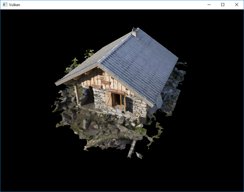
It's not a dramatic difference, since our scene is so simple. There are subtle differences if you look closely.
没什么打的区别,因为我们的场景太简单了。如果你靠近观看,会有微妙的区别。
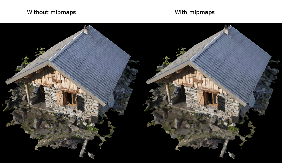
The most noticeable difference is the writing on the signs. With mipmaps, the writing has been smoothed. Without mipmaps, the writing has harsh edges and gaps from Moiré artifacts.
最引人注意的区别是。有mipmap,写入被平滑了。没有mipmap,Moiré艺术品写入会有刺目的边界和裂缝。
You can play around with the sampler settings to see how they affect mipmapping. For example, by changing minLod, you can force the sampler to not use the lowest mip levels:
你可以鼓捣鼓捣采样器设置to看看它们如何影响mipmap。例如,通过修改minLod,你可以强制采样器不使用最低的mip层:
samplerInfo.minLod = static_cast<float>(mipLevels / 2);
These settings will produce this image:
这些设置会产生这样的结果:
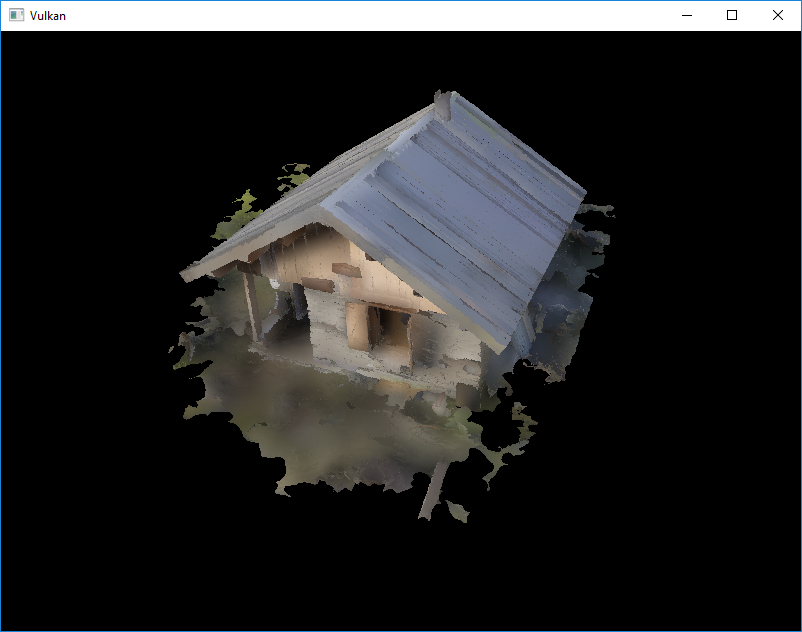
This is how higher mip levels will be used when objects are further away from the camera.
这就是更高的mip层会被使用的结果when对象原理摄像机。
C++ code / Vertex shader / Fragment shader