上一節描述了bootsect.s的過程,這裡將接著bootsect.s跳到0x90200地址的setup模塊進入講述。
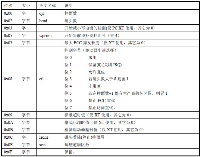
當執行到setup,原來bootsect的空間會被setup獲取的參數覆蓋。原bootsect的空間被定義成如下:

經過setup模塊的操作后,原bootsect的空間將被填寫上表的數據。
"宏"定義、讀指針屬性及內存大小:
 1 !
 2 !    setup.s        (C) 1991 Linus Torvalds
 3 !
 4 ! setup.s is responsible for getting the system data from the BIOS,
 5 ! and putting them into the appropriate places in system memory.
 6 ! both setup.s and system has been loaded by the bootblock.
 7 !
 8 ! This code asks the bios for memory/disk/other parameters, and
 9 ! puts them in a "safe" place: 0x90000-0x901FF, ie where the
10 ! boot-block used to be. It is then up to the protected mode
11 ! system to read them from there before the area is overwritten
12 ! for buffer-blocks.
  ! setup.s 负责从BIOS中获取系统数据,并将这些数据放到系统内存的适当地方。
  ! 此时setup.s和system已经由bootsect引导块加载到内存中。
  ! 这段代码询问bios有关内存/磁盘/其它参数,并将这些参数放到一个“安全的”地方:0x90000-0x901FF,
  ! 也即原来bootsect代码块曾经在的地方,然后在被缓冲块覆盖掉之前由保护模式的system读取。
13 !
14
15 ! NOTE! These had better be the same as in bootsect.s!
   ! 以下这些参数最好和bootsect.s 中的相同!
16
17 INITSEG  = 0x9000    ! we move boot here - out of the way    ! bootsect所在的段地址
18 SYSSEG   = 0x1000    ! system loaded at 0x10000 (65536).     ! system所在的段地址
19 SETUPSEG = 0x9020    ! this is the current segment        ! setup所在的段地址
20
21 .globl begtext, begdata, begbss, endtext, enddata, endbss
22 .text
23 begtext:
24 .data
25 begdata:
26 .bss
27 begbss:
28 .text
29
30 entry start
31 start:
32
33 ! ok, the read went well so we get current cursor position and save it for
34 ! posterity.
  ! ok,整个读磁盘过程都正常,现在将光标位置保存以备今后使用。
35
36     mov    ax,#INITSEG    ! this is done in bootsect already, but...
37     mov    ds,ax       ! 這裡再次設置ds段寄存器的值
38     mov    ah,#0x03       ! read cursor pos  ! 功能號為3
39     xor    bh,bh        ! 清零bh
40     int    0x10           ! save it in known place, con_init fetches
                  ! Read Cursor Position and Size
                 ! AH = 03
                 ! BH = video page
                 ! on return:
                  ! CH = cursor starting scan line (low order 5 bits)
                 ! CL = cursor ending scan line (low  order 5 bits)
                 ! DH = row
                 ! DL = column
41     mov    [0],dx         ! it from 0x90000.
                  ! 在0x90000寫入光標位置(dx,低地址為column,高地址為row)
42
43 ! Get memory size (extended mem, kB)  ! 取擴展內存大小
44
45     mov    ah,#0x88
46     int    0x15      ! Extended Memory Size Determination
                 ! AH = 88h
                 ! on return:
                 ! CF = 80h for PC, PCjr
                 ! = 86h for XT and Model 30
                 ! = other machines, set for error, clear for  success
                 ! AX = number of contiguous 1k blocks of memory starting at address 1024k (100000h)
47     mov    [2],ax      ! 在0x90002寫入擴展內存大小
獲取顯示信息:
 1 ! Get video-card data:
 2
 3     mov    ah,#0x0f
 4     int    0x10      ! Get Video State
                 ! AH = 0Fh
                 ! on return:
                 ! AH = number of screen columns
                 ! AL = mode currently set (see VIDEO MODES)
                 ! BH = current display page
 5     mov    [4],bx        ! bh = display page  ! 0x90004
 6     mov    [6],ax        ! al = video mode, ah = window width  ! 0x90006
 7
 8 ! check for EGA/VGA and some config parameters
 9
10     mov    ah,#0x12
11     mov    bl,#0x10
12     int    0x10      ! Video Subsystem Configuration (EGA/VGA)  (這個BIOS中斷好複雜,我只貼出這裡的功能部份,具體可看本章第一節末尾的網址)
                 ! AH = 12h
                 ! BL = 10h  return video configuration information
                 ! on return:
                 ! BH = 0 if color mode in effect
                 !   = 1 if mono mode in effect
                 ! BL = 0 if 64k EGA memory
                 !    = 1 if 128k EGA memory
                 !    = 2 if 192k EGA memory
                 !    = 3 if 256k EGA memory
                 ! CH = feature bits
                 ! CL = switch settings
13     mov    [8],ax      ! 0x90008
14     mov    [10],bx     ! 0x9000A
15     mov    [12],cx     ! 0x9000C
磁盤操作:
直到這裡,才知道,BIOS在初始化時,會在0x00000處放置一個自身用的中斷向量表(1kb大小)。爲什麽要把system放到0x10000的謎底終於解開,因為在bootsect和setup的執行中,還需要使用BIOS中斷,所以不能把中斷向量表給覆蓋掉(不能把system放到0x00000中)。下邊的操作與BIOS的中斷向量表有關。我在網上找到一個BIOS中斷向量的定義,可自行查看。
 1 ! Get hd0 data
 2
 3     mov    ax,#0x0000
 4     mov    ds,ax      ! 把ds設成0x0000
 5     lds    si,[4*0x41]   ! 這裡0x41是BIOS硬盤0的中斷向量表,4是中斷號與絕對地址的映射關係,0x41對應0x104的地址,
                 ! 把中斷向量表指向地址給si
 6     mov    ax,#INITSEG
 7     mov    es,ax      ! 把es設成0x9000
 8     mov    di,#0x0080    ! di指向第一個硬盤描述表地址(0x90080)
 9     mov    cx,#0x10     ! 賦值16,用於循環。(硬盤描述表為16字節)
10     rep
11     movsb          ! 把BIOS中的硬盤0中斷向量表的數據移動到0x90080,下同
12
13 ! Get hd1 data
14
15     mov    ax,#0x0000
16     mov    ds,ax
17     lds    si,[4*0x46]   ! 0x46是BIOS硬盤1的中斷向量表
18     mov    ax,#INITSEG
19     mov    es,ax
20     mov    di,#0x0090   ! di指向第二個硬盤描述表地址(0x90090)
21     mov    cx,#0x10
22     rep
23     movsb
24
25 ! Check that there IS a hd1 :-)
26
27     mov    ax,#0x01500
28     mov    dl,#0x81
29     int    0x13       ! Read DASD Type (XT BIOS from 1/10/86 & newer)
                 ! AH = 15h
                 ! DL = drive number (0=A:, 1=2nd floppy, 80h=drive 0, 81h=drive 1)
                 ! on return:
                 ! AH = 00 drive not present
                 !    = 01 diskette, no change detection present
                 !    = 02 diskette, change detection present
                 !    = 03 fixed disk present
                 ! CX:DX = number of fixed disk sectors; if 3 is returned in AH
                 ! CF = 0 if successful
                 !    = 1 if error
30     jc    no_disk1     ! 操作失敗,跳到no_disk1
31     cmp    ah,#3      ! 判斷是否為固定磁盤,
32     je    is_disk1     ! 如果是跳到is_disk1執行
33 no_disk1:
34     mov    ax,#INITSEG
35     mov    es,ax
36     mov    di,#0x0090
37     mov    cx,#0x10
38     mov    ax,#0x00
39     rep
40     stosb          ! 把al中的值賦給di指向的地址,清零硬盤2的信息
41 is_disk1:
42
43 ! now we want to move to protected mode ...  ! 進入保護模式
44
45     cli            ! no interrupts allowed !  ! 禁止可屏蔽中斷
移動System模塊:
 1 ! first we move the system to it's rightful place
 2
 3     mov    ax,#0x0000
 4     cld                ! 'direction'=0, movs moves forward  ! 清除方向標誌
 5 do_move:
 6     mov    es,ax         ! destination segment
 7     add    ax,#0x1000   ! 段地址移動下一段(由於一段只能訪問64kb,所以要移動段地址到下一內存空間,再繼續訪問)
 8     cmp    ax,#0x9000   ! 判斷是否到達數據末端
 9     jz    end_move      ! 到達數據末端
10     mov    ds,ax         ! source segment
11     sub    di,di      ! 清零di
12     sub    si,si      ! 清零si
13     mov    cx,#0x8000   ! 設置循環次數(段移動,由於使用字移動,所以0x8000 * 2 = 0x10000個字的大小,剛好一段的長度)
14     rep
15     movsw          ! 字移動(從si到di)
16     jmp    do_move     ! 無條件跳轉
17
18 ! then we load the segment descriptors
19
20 end_move:
21     mov    ax,#SETUPSEG   ! right, forgot this at first. didn't work :-)
22     mov    ds,ax      ! ds設成0x9020
23     lidt    idt_48        ! load idt with 0,0            ! 載入中斷描述符表,idt_48變量在後面描述
24     lgdt    gdt_48        ! load gdt with whatever appropriate  ! 載入全局描述符表,gdt_48變量在後面描述
使能A20、配置中斷控制器,并進入system:
這裡主要是對一些外部控制器的配置,最后進入保護模式使CPU進入保護模式執行(保護模式可以更好地尋址關於實模式與保護模式可在這裡瞭解,關於A20的可在這裡瞭解)
! that was painless, now we enable A20
! 以上的操作很简单,现在我们开启A20地址线。参见程序列表后有关A20信号线的说明。
! 关于所涉及到的一些端口和命令,可参考kernel/chr_drv/keyboard.S 程序后对键盘接口的说明。
! 這步的操作,據說在現在的硬件中已經不再適用,不管適用與否,這裡只是對這一過程的瞭解。
    call   empty_8042    ! 等待输入缓冲器空。
                 ! 只有当输入缓冲器为空时才可以对其进行操作。
    mov    al,#0xD1        ! command write
    out    #0x64,al     ! 0x64是8042的命令端口,向0x64寫入0xD1,表示準備寫Output端口。
                ! 隨後通過0x60端口寫入的字節,會被放置在Output Port中。
    call   empty_8042
    mov    al,#0xDF        ! 這數值的具體含義已經很難找出了,但大概就是用於使能A20的
    out    #0x60,al     ! 被寫入的數據
    call   empty_8042

! well, that went ok, I hope. Now we have to reprogram the interrupts :-(
! we put them right after the intel-reserved hardware interrupts, at
! int 0x20-0x2F. There they won't mess up anything. Sadly IBM really
! messed this up with the original PC, and they haven't been able to
! rectify it afterwards. Thus the bios puts interrupts at 0x08-0x0f,
! which is used for the internal hardware interrupts as well. We just
! have to reprogram the 8259's, and it isn't fun.

! 8259可編程中斷控制器,初始化如下:
! Initialization
! 1. write ICW1 to port 20h
! 2. write ICW2 to port 21h
! 3. if ICW1 bit D1=1  do nothing
     if ICW1 bit D1=0  write ICW3 to port 20h
! 4. write ICW4 to port 21h
! 5. OCW's can follow in any order
    mov    al,#0x11        ! initialization sequence  ! ICW1。表示邊沿觸發、多片8259級聯、最後要發送ICW4命令字
                 !|7|6|5|4|3|2|1|0|  ICW1
                 ! | | | | | | | `---- 1=ICW4 is needed, 0=no ICW4 needed
                 ! | | | | | | `----- 1=single 8259, 0=cascading 8259's
                 ! | | | | | `------ 1=4 byte interrupt vectors, 0=8 byte int vectors
                 ! | | | | `------- 1=level triggered mode, 0=edge triggered mode
                 ! | | | `-------- must be 1 for ICW1 (port must also be 20h or A0h)
                 ! `------------- must be zero for PC systems
    out    #0x20,al        ! send it to 8259A-1     ! 向8259A-1寫入ICW1

! 下面定义的两个字是直接使用机器码表示的两条相对跳转指令,起延时作用。
! 0xeb是直接近跳转指令的操作码,带1个字节的相对位移值。因此跳转范围是-127到127。
! CPU通过把这个相对位移值加到EIP寄存器中就形成一个新的有效地址。此时EIP指向下一条被执行的指令。
! 执行时所花费的CPU时钟周期数是7至10个。0x00eb表示跳转值是0的一条指令,因此还是直接执行下一条指令。
! 这两条指令共可提供14-20个CPU 时钟周期的延迟时间。在as86中没有表示相应指令的助记符,
! 因此Linus在setup.s等一些汇编程序中就直接使用机器码来表示这种指令。
! 另外,每个空操作指令NOP的时钟周期数是3个,因此若要达到相同的延迟效果就需要6至7个NOP指令。
    .word  0x00eb,0x00eb   ! jmp $+2, jmp $+2
    out    #0xA0,al        ! and to 8259A-2         ! 向8259A-2寫入ICW1

    .word  0x00eb,0x00eb
    mov    al,#0x20        ! start of hardware int's (0x20) ! ICW2
                ! |7|6|5|4|3|2|1|0|  ICW2
                !  | | | | | `-------- 000= on 80x86 systems
                !  `-----------------  A7-A3 of 80x86 interrupt vector
    out    #0x21,al     ! 向8259A-1寫入ICW2
    .word  0x00eb,0x00eb
    mov    al,#0x28        ! start of hardware int's 2 (0x28)
    out    #0xA1,al     ! 向8259A-2寫入ICW2

    .word  0x00eb,0x00eb
    mov    al,#0x04        ! 8259-1 is master  ! ICW3 for master
                ! |7|6|5|4|3|2|1|0|  ICW3 for Master Device
                ! | | | | | | | `---- 1=interrupt request 0 has slave, 0=no slave
                ! | | | | | | `----- 1=interrupt request 1 has slave, 0=no slave
                ! | | | | | `------ 1=interrupt request 2 has slave, 0=no slave
                ! | | | | `------- 1=interrupt request 3 has slave, 0=no slave
                ! | | | `-------- 1=interrupt request 4 has slave, 0=no slave
                ! | | `--------- 1=interrupt request 5 has slave, 0=no slave
                ! | `---------- 1=interrupt request 6 has slave, 0=no slave
                ! `----------- 1=interrupt request 7 has slave, 0=no slave
    out    #0x21,al     ! 向8259A-1寫入ICW3
    .word  0x00eb,0x00eb
    mov    al,#0x02        ! 8259-2 is slave  !ICW3 for slave
                !|7|6|5|4|3|2|1|0|  ICW3 for Slave Device
                ! | | | | | `-------- master interrupt request slave is attached to
                ! `----------------- must be zero
    out    #0xA1,al     ! 向8259A-2寫入ICW3

    .word  0x00eb,0x00eb
    mov    al,#0x01        ! 8086 mode for both  ! ICW4
                ! |7|6|5|4|3|2|1|0|  ICW4
                ! | | | | | | | `---- 1 for 80x86 mode, 0 = MCS 80/85 mode
                ! | | | | | | `----- 1 = auto EOI, 0=normal EOI
                ! | | | | `-------- slave/master buffered mode (see below)
                ! | | | `--------- 1 = special fully nested mode (SFNM), 0=sequential
                ! `-------------- unused (set to zero)
    out    #0x21,al     ! 向8259A-1寫入ICW4
    .word  0x00eb,0x00eb
    out    #0xA1,al     ! 向8259A-2寫入ICW4

    .word  0x00eb,0x00eb
    mov    al,#0xFF        ! mask off all interrupts for now
                ! |7|6|5|4|3|2|1|0|  OCW1 - IMR Interrupt Mask Register
                ! | | | | | | | `---- 0 = service IRQ0, 1 = mask off
                ! | | | | | | `----- 0 = service IRQ1, 1 = mask off
                ! | | | | | `------ 0 = service IRQ2, 1 = mask off
                ! | | | | `------- 0 = service IRQ3, 1 = mask off
                ! | | | `-------- 0 = service IRQ4, 1 = mask off
                ! | | `--------- 0 = service IRQ5, 1 = mask off
                ! | `---------- 0 = service IRQ6, 1 = mask off
                ! `----------- 0 = service IRQ7, 1 = mask off
    out    #0x21,al     ! 向8259A-1寫入OCW1
    .word  0x00eb,0x00eb
    out    #0xA1,al     ! 向8259A-2寫入OCW1

! well, that certainly wasn't fun :-(. Hopefully it works, and we don't
! need no steenking BIOS anyway (except for the initial loading :-).
! The BIOS-routine wants lots of unnecessary data, and it's less
! "interesting" anyway. This is how REAL programmers do it.
!
! Well, now's the time to actually move into protected mode. To make
! things as simple as possible, we do no register set-up or anything,
! we let the gnu-compiled 32-bit programs do that. We just jump to
! absolute address 0x00000, in 32-bit protected mode.

! 这里设置进入32位保护模式运行。首先加载机器状态字(lmsw-Load Machine Status Word),
! 也称控制寄存器CR0,其比特位0置1将导致CPU 工作在保护模式。
    mov    ax,#0x0001   ! protected mode (PE) bit  ! 這裡是機器狀態字
              ! |31|30-5|4|3|2|1|0|  Machine Status Word|
              ! |  | | | | `---- Protection Enable (PE)
              ! |   |  | | | `----- Math Present (MP)
              ! |   |  | | `------ Emulation (EM)
              ! |   |  | `------- Task Switched (TS)
              ! |   |  `-------- Extension Type (ET)
              ! |   `---------- Reserved
              ! `------------- Paging (PG)
    lmsw   ax           ! This is it!  ! 載入機器狀態字
    jmpi   0,8          ! jmp offset 0 of segment 8 (cs)
! 到这里已经将system模块移动到0x00000开始的地方,所以这里的偏移地址是0。
! 这里的段值的8已经是保护模式下的段选择符了,用于选择描述符表和描述符表项以及所要求的特权级。
! 段选择符长度为16位(2字节);位0-1表示请求的特权级0-3,linux操作系统只用到两级:0级(系统级)和3级(用户级);
! 位2用于选择全局描述符表(0)还是局部描述符表(1);位3-15是描述符表项的索引,指出选择第几项描述符。
! 所以段选择符8(0b0000,0000,0000,1000)表示请求特权级0、使用全局描述符表中的第1项,
! 该项指出代码的基地址是0(参见gdt定義),因此这里的跳转指令就会去执行system中的代码。
中斷、全局描述符表:
由於保護模式下運行需要中斷描述符表及全局描述符表,但由於這兩個表都未被正式初始化,這裡將是定義一個臨時的描述符表,使CPU進入保護模式時,能正常運行。
 1 ! This routine checks that the keyboard command queue is empty
 2 ! No timeout is used - if this hangs there is something wrong with
 3 ! the machine, and we probably couldn't proceed anyway.
 4 empty_8042:
 5     .word 0x00eb,0x00eb  ! 前面有提到,用於延時
 6     in    al,#0x64    ! 8042 status port    ! 用al讀取8042狀態
 7     test  al,#2       ! is input buffer full?
 8     jnz   empty_8042  ! yes - loop        ! 如果非空繼續循環
 9     ret         ! 返回調用
10
11 gdt:
    ! 全局描述符表开始处。描述符表由多个8字节长的描述符项组成。这里给出了3个描述符项。
    ! 第1项无用(12行),但须存在。
    ! 第2项是系统代码段描述符(14-17行),
    ! 第3项是系统数据段描述符(19-22行)。每个描述符的具体含义参见列表后说明。
12     .word    0,0,0,0       ! dummy    ! 第1个描述符,不用。
13
    ! 这里在gdt表中的偏移量为0x08,当加载代码段寄存器(段选择符)时,使用的是这个偏移值。
14     .word    0x07FF        ! 8Mb - limit=2047 (2048*4096=8Mb)
15     .word    0x0000        ! base address=0
16     .word    0x9A00        ! code read/exec
17     .word    0x00C0        ! granularity=4096, 386
18
    ! 这里在gdt表中的偏移量是0x10,当加载数据段寄存器(如ds等)时,使用的是这个偏移值。
19     .word    0x07FF        ! 8Mb - limit=2047 (2048*4096=8Mb)
20     .word    0x0000        ! base address=0
21     .word    0x9200        ! data read/write
22     .word    0x00C0        ! granularity=4096, 386
23
24 idt_48:
25     .word    0             ! idt limit=0
26     .word    0,0           ! idt base=0L
27
28 gdt_48:
29     .word    0x800         ! gdt limit=2048, 256 GDT entries  ! 全局表长度为2k字节,因为每8字节组成一个段描述符项,所以表中共可有256 项。
30     .word    512+gdt,0x9   ! gdt base = 0X9xxxx  ! 4个字节构成的内存线性地址:(0x0009<<16) + 0x0200 + gdt,即0x90200 + gdt(即程序中的gdt:的偏移地址)
31
32 .text
33 endtext:
34 .data
35 enddata:
36 .bss
37 endbss:
中斷描述符表和中斷描述符表結構相似,在這裡網址有說明,不過在說段類型時感覺怪怪的,其他的都基本符合,關於段類型的不好找,以後找到,再貼上。
硬盤描述表: