本文参考自教程,并加上自己的一些心得体会。
0.生成三角形面片
一块草地由若干根草组成,每根草其实可以看作是一个三角形面片。为了生成三角形面片,我们借助geometry shader的力量,去修改输入的顶点信息:
[maxvertexcount(3)]
void geo(triangle v2g IN[3], inout TriangleStream<g2f> tristream)
{
	tristream.Append(generateGeoVertex(IN[0]));
	tristream.Append(generateGeoVertex(IN[0]));
	tristream.Append(generateGeoVertex(IN[0]));
}
如何确定生成三角形面片的position信息呢?这里我们选择在切线空间中去生成position。之所以选择切线空间而不是物体空间,是因为我们希望最后生成的草是生长在物体表面的,即与物体表面垂直,与物体本身是什么形状是无关的。通过输入的顶点信息,即可构造出所需要的TBN矩阵:
        float4 vertex = IN[0].vertex;
        float4 tangent = IN[0].tangent;
        float3 normal = IN[0].normal;
        float3 binormal = cross(normal, tangent) * tangent.w;
        float3x3 tangentToLocal =
        {
            tangent.x, binormal.x, normal.x,
            tangent.y, binormal.y, normal.y,
            tangent.z, binormal.z, normal.z,
        };
Unity提供的tangent向量中的w分量用于确定副切线binormal的方向。接下来,就可以将生成的三角形面片的切线坐标转换到裁剪坐标系输出给frag shader:
    g2f generateGeoVertex(float3 originPos, float width, float forward, float height, float2 uv, float3x3 tangentToLocal)
    {
        float3 tangentPos = float3(width, forward, height);
        float3 localPos = originPos + mul(tangentToLocal, tangentPos);
        g2f o;
        o.uv = uv;
        o.pos = UnityObjectToClipPos(localPos);
        return o;
    }
假设生成的三角形切线坐标为(-0.5, 0, 0),(0.5, 0, 0),(0, 1, 0),生成的效果如下:
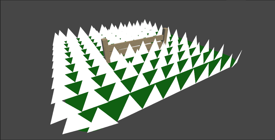
显而易见有一些细节需要完善,让我们来逐一解决。
1.完善草的细节
我们希望,草的颜色是渐变的绿色,底部的颜色最深,顶部的颜色最浅。因此,我们可以借助纹理坐标的y来代表颜色的深浅程度:
            fixed4 frag (g2f i) : SV_Target
            {
                fixed4 col = lerp(_BottomColor, _TopColor, i.uv.y);
                return col;
            }
然后在面板上调好颜色,效果如下:

看上去有了草的气息。但是现在看上去太死板了,每个草的面向完全一致,需要加些随机因素,让每个草的面向发生不同的偏转,也就是在切线坐标系中,让它们的坐标绕z轴旋转一个随机的角度:
float3x3 randomFacingMatrix = angleAxis3x3(rand(vertex.xyz) * TWO_PI, float3(0, 0, 1));
float3x3 mat = mul(tangentToLocal, randomFacingMatrix);
看上去好了一些。不过现在来看每一棵草都是笔直的,也比较生硬,需要给它们随机俯仰一个角度:
float3x3 ramdomForwardMatrix = angleAxis3x3(rand(vertex.zyx) * _BendRotationRandom * HALF_PI, float3(-1, 0, 0));
float3x3 mat = mul(mul(tangentToLocal, randomFacingMatrix), ramdomForwardMatrix);

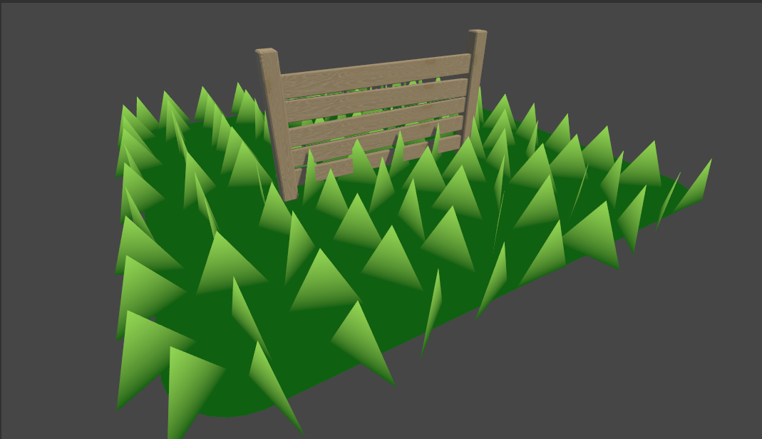
接下来,我们需要处理每棵草的宽度和高度,现在每棵草显得太大了,也要限制下宽高阈值,然后随机一下:
float randomWidth = (2 * rand(vertex.xzy) - 1) * _BladeWidthRandom + _BladeWidth;
float randomHeight = (2 * rand(vertex.yzx) - 1) * _BladeHeightRandom + _BladeHeight;

现在草终于有草的样子了,但是看上去也太过于稀疏了。接下来我们要借助tessellation的力量,扩充整体的顶点数量。
2.tessellation增加顶点
在渲染管线中我们只能指定tessellation输入的顶点信息,和具体输出的顶点信息,中间如何tessellation的过程是由硬件控制的。有关tessellation的文章可以查看这篇。为了实现tessellation,我们需要引入hull shader和domain shader,并声明用来告诉硬件如何细分顶点的TessellationFactors结构:
struct TessellationFactors
{
	float edge[3] : SV_TessFactor;
	float inside : SV_InsideTessFactor;
};

TessellationFactors patchConstantFunction(InputPatch<v2g, 3> patch)
{
    TessellationFactors f;
    f.edge[0] = _TessellationUniform;
    f.edge[1] = _TessellationUniform;
    f.edge[2] = _TessellationUniform;
    f.inside = _TessellationUniform;
    return f;
}

[UNITY_domain("tri")]
[UNITY_patchconstantfunc("patchConstantFunction")]
[UNITY_partitioning("integer")]
[UNITY_outputtopology("triangle_cw")]
[UNITY_outputcontrolpoints(3)]
v2g hull (InputPatch<v2g, 3> patch, uint id : SV_OutputControlPointID)
{
	return patch[id];
}

[UNITY_domain("tri")]
v2g domain(TessellationFactors factors, OutputPatch<v2g, 3> patch, float3 barycentricCoordinates : SV_DomainLocation)
{
    v2g v;
    v.vertex = patch[0].vertex * barycentricCoordinates.x + patch[1].vertex * barycentricCoordinates.y + patch[2].vertex * barycentricCoordinates.z;
    v.tangent = patch[0].tangent * barycentricCoordinates.x + patch[1].tangent * barycentricCoordinates.y + patch[2].tangent * barycentricCoordinates.z;
    v.normal = patch[0].normal * barycentricCoordinates.x + patch[1].normal * barycentricCoordinates.y + patch[2].normal * barycentricCoordinates.z;
    v.uv = patch[0].uv * barycentricCoordinates.x + patch[1].uv * barycentricCoordinates.y + patch[2].uv * barycentricCoordinates.z;

    return v;
}
patchConstantFunction用来设置factors结构的值。具体tessellation factors中的edge和inside分量是如何影响顶点划分的,可以参考这篇知乎问答。
做完这些后,我们将_TessellationUniform的值调大试试:

3.让草动起来
现在看上去已经有了草地的雏形,但它们都还是静止的。接下来,我们要加一点风的元素,让草动起来。
实现起来也不是很麻烦,就是根据时间的变化,对一张代表风的贴图进行连续采样,根据采样点信息计算出风力和风向,然后得到对应的旋转矩阵,应用在每棵草上:
        float2 uv = vertex.xz * _WindDistortionMap_ST.xy + _WindDistortionMap_ST.zw + _WindFrequency * _Time.y;
        float2 windSample = (2 * tex2Dlod(_WindDistortionMap, float4(uv, 0, 0)).xy - 1) * _WindStrength;
        float3 wind = normalize(float3(windSample, 0));
        float3x3 windMatrix = angleAxis3x3(windSample * PI, wind);
        float3x3 mat = mul(mul(mul(tangentToLocal, windMatrix), randomFacingMatrix), ramdomForwardMatrix);
需要注意的是,由于这些工作都是在geometry shader完成的,因而要使用tex2Dlod而不是tex2D方法进行采样,否则会出错,原因可以参考这个链接:
The error here is that you're trying to sample from a texture in a vertex shader the way you would in a fragment or pixel shader.
Vertex texture fetches are a little bit special. They're only supported in Shader Model 3 and up,
and they're unable to use the tex2d() function.
That may sound odd, but tex2D() is really a shortcut that says "figure out the right mip level to sample automatically"
- in a fragment shader this is done using implicit derivatives, but those aren't available at the vertex stage.
So, we need to use the more explicit tex2dlod() form (which works at both the vertex and fragment stages).
This takes a 4-component vector, whose x and y are the familiar texture coordinates in uv space,
and w indicates which mip level to sample from (0 being the highest resolution available).

有了随风摆动的效果之后,我们发现每棵草还是太有三角形几何体的特征,于是我们在geometry shader中将输出的顶点增加为7个,并在切线空间中修改顶点的y值,使得它们带有一定形状的扭曲,最顶端的扭曲程度越大。
另外,我们注意到,每棵草的根部是不应该有俯仰和扭曲,还有随风摆动的,不然根部很可能会被旋转到地底里去。所以,我们根据了每棵草顶点的不同区分了变换矩阵:
#define BLADE_SEGMENTS 3
[maxvertexcount(2 * BLADE_SEGMENTS + 1)]
void geo(triangle v2g IN[3], inout TriangleStream<g2f> tristream)
{
	float3x3 widthMat = mul(tangentToLocal, randomFacingMatrix);
	float3x3 heightMat = mul(mul(mul(tangentToLocal, windMatrix), randomFacingMatrix), ramdomForwardMatrix);

	for(int i = 0; i < BLADE_SEGMENTS; i++)
    {
    	float t = (float)i / BLADE_SEGMENTS;
    	float width = randomWidth * (1 - t);
    	float forward = randomForward * pow(t, _BladeCurve);
    	float height = randomHeight * t;
    	float3x3 mat = i == 0 ? widthMat : heightMat;

		tristream.Append(generateGeoVertex(vertex, -0.5 * width, forward, height, float2(t, t), mat));
		tristream.Append(generateGeoVertex(vertex, 0.5 * width, forward, height, float2(1 - t, t), mat));
	}
		tristream.Append(generateGeoVertex(vertex, 0, randomForward, randomHeight, float2(0.5, 1), heightMat));
}

4.光照与阴影
最后,我们要为草加上光照和阴影。阴影分为产生阴影和接收阴影两部分,产生阴影需要新增一个pass,写入shadow map:
        Pass
		{
			Tags
			{
				"LightMode" = "ShadowCaster"
			}

			CGPROGRAM
            #pragma multi_compile_shadowcaster

			float4 frag(g2f i) : SV_Target
			{
				SHADOW_CASTER_FRAGMENT(i)
			}

			ENDCG
		}
接收阴影使用Unity提供的SHADOW_COORDS,TRANSFER_SHADOW,SHADOW_ATTENUATION即可实现,配合最基本的漫光照模型,修改frag代码:
        Pass
        {
            CGPROGRAM

            fixed4 frag (g2f i, fixed facing : VFACE) : SV_Target
            {
                float3 normal = facing > 0 ? i.normal : -i.normal;
                float shadow = SHADOW_ATTENUATION(i);
                float nDotL = saturate(dot(normal, _WorldSpaceLightPos0)) * shadow;
                float3 ambient = ShadeSH9(float4(normal, 1));
                float4 lightColor = float4(ambient + nDotL * _LightColor0, 1);
                fixed4 col = lerp(_BottomColor, _TopColor * lightColor, i.uv.y);
                return col;
            }
            ENDCG
        }
这里我们假定了只有顶端的颜色才会和光照颜色融合,如果底端也融合的话,整棵草的颜色会偏暗。同时,为了支持深度偏差,使用Unity提供的UnityApplyLinearShadowBias:
#if UNITY_PASS_SHADOWCASTER
	    // Applying the bias prevents artifacts from appearing on the surface.
	    o.pos = UnityApplyLinearShadowBias(o.pos);
#endif
最终效果如下:

如果你觉得我的文章有帮助,欢迎关注我的微信公众号(大龄社畜的游戏开发之路)-