一、概述
串行CPU工作流程
串行CPU的时序流程如下图所示:取指、译码、执行、回写。 其中,取指、回写是与存储器打交道;而译码与执行则是CPU内部自个儿的操作。

我们究竟想要CPU干什么?
CPU的最终目的不是计算,不是把计算结果存储在通用寄存器中。CPU的最终目的应该是按照次序不断的修改存储设备的存储内容。
利用CPU来显示,来唱歌······只有CPU把计算的结果存放在存储设备中的时候(姑且把修改特殊功能寄存器的值也看做是修改存储器的内容),才能实现这些功能。正如假设霍金有个很好的头脑来思考问题,但是假如他不能将思考到的东西通过某种方式告诉别人,那么没人会注意他。
提出这个问题,主要是想要你关注“回写”的重要性。
二、各组成模块
本文的所有VHDL程序摘自《开放式实验CPU设计》第二章 “16位实验CPU设计实例”。
1、通用寄存器组成部分 (regfile)


  1 --实验6.9——实验CPU:通用寄存器组
  2 library IEEE;
  3 use IEEE.STD_LOGIC_1164.ALL;
  4
  5 entity regfile is
  6 Port (  DR:         in std_logic_vector(1 downto 0);
  7         SR:         in std_logic_vector(1 downto 0);
  8         reset:      in std_logic;
  9         DRWr:       in std_logic;
 10         clk:         in std_logic;
 11         d_input:     in  std_logic_vector(15 downto 0);
 12         DR_data:    out std_logic_vector(15 downto 0);
 13         SR_data:      out std_logic_vector(15 downto 0)
 14       );
 15 end regfile;
 16
 17
 18 architecture struct of regfile is
 19 -- components
 20 -- 16 bit Register for register file
 21 component reg
 22 port    (
 23         clr:     in    std_logic;
 24         D:         in    std_logic_vector(15 downto 0);
 25         clock:     in    std_logic;
 26         write:  in    std_logic;
 27         sel:     in    std_logic;
 28         Q:         out std_logic_vector(15 downto 0)
 29         );
 30 end component;
 31
 32 -- 2 to 4 Decoder
 33 component  decoder_2_to_4
 34     port(
 35         sel:     in  std_logic_vector(1 downto 0);
 36         sel00:     out std_logic;
 37         sel01:     out std_logic;
 38         sel02:     out std_logic;
 39         sel03:     out std_logic
 40         );
 41 end component;
 42
 43 -- 4 to 1 line multiplexer
 44 component mux_4_to_1
 45 port (
 46     input0,
 47     input1,
 48     input2,
 49     input3:  in std_logic_vector(15 downto 0);
 50     sel:     in std_logic_vector(1 downto 0);
 51     out_put: out std_logic_vector(15 downto 0));
 52 end component;
 53
 54
 55 signal reg00, reg01, reg02, reg03
 56             :std_logic_vector(15 downto 0);
 57
 58 signal sel00 ,sel01 ,sel02 ,sel03
 59             : std_logic;
 60
 61 begin
 62 Areg00: reg port map(
 63         clr            =>  reset,
 64         D            =>    d_input ,
 65         clock        =>    clk ,
 66         write        =>    DRWr ,
 67         sel            =>    sel00 ,
 68         Q            =>  reg00
 69         );
 70
 71 Areg01: reg port map(
 72         clr            =>  reset,
 73         D            =>    d_input ,
 74         clock        =>    clk ,
 75         write        =>    DRWr ,
 76         sel            =>    sel01 ,
 77         Q            =>  reg01
 78         );
 79
 80 Areg02: reg port map(
 81         clr            =>  reset,
 82         D            =>  d_input ,
 83         clock        =>    clk ,
 84         write        =>    DRWr ,
 85         sel            =>    sel02 ,
 86         Q            =>  reg02
 87         );
 88
 89 Areg03: reg port map(
 90         clr            =>  reset,
 91         D            =>    d_input ,
 92         clock        =>    clk ,
 93         write        =>    DRWr ,
 94         sel            =>    sel03 ,
 95         Q            =>  reg03
 96         );
 97
 98 -- decoder
 99 des_decoder: decoder_2_to_4 port map
100         (
101         sel     => DR,
102         sel00     => sel00 ,
103         sel01     => sel01 ,
104         sel02     => sel02 ,
105         sel03     => sel03
106         );
107
108 mux1: mux_4_to_1 PORT MAP(
109     Input0 => reg00 ,
110     Input1 => reg01 ,
111     Input2 => reg02 ,
112     Input3 => reg03 ,
113     sel => DR ,
114     out_put => DR_data
115     );
116
117 mux2: mux_4_to_1 PORT MAP(
118     input0     => reg00 ,
119     input1     => reg01 ,
120     input2     => reg02 ,
121     input3     => reg03 ,
122     sel     => SR ,
123     out_put => SR_data
124     );
125
126 end struct;

如上图所示:
(1)通用寄存器组是即可以读(两个口可以读),又可以写(只有一个口)
(2)通用寄存器组是CPU暂存数据的单元;这里还包括程序状态标志位,跳转指令会用到
2、取指部分 (instru_fetch)
 1 library ieee, my_lib;
 2 use ieee.std_logic_1164.all;
 3 use ieee.std_logic_arith.all;
 4 use ieee.std_logic_unsigned.all;
 5 use my_lib.exp_cpu_components.all;
 6
 7 entity instru_fetch  is
 8     port(reset,clk:     in std_logic;
 9         data_read:     in std_logic_vector(15 downto 0); --存储器读出的数
10         lj_instruct: in std_logic; --长转移指令
11         DW_intruct:     in std_logic;
12         c_z_j_flag:  in std_logic; --为1时进行条件转移
13         sjmp_addr:     in std_logic_vector(15 downto 0); --条件转移指令的转移地址
14         t1,t2,t3:      buffer std_logic;
15         pc:             buffer std_logic_vector(15 downto 0);
16         pc_inc:         buffer std_logic_vector(15 downto 0);
17         IR:             out std_logic_vector(15 downto 0)
18         );
19 end instru_fetch;
20
21 architecture behav of instru_fetch is
22 signal start:    std_logic;
23
24 begin
25 IR_poc: process(reset,t2)
26 begin
27     if reset = '0' then
28         IR <= x"7000";  --nop指令
29     elsif t2'event and t2 = '1' then
30         IR <= data_read;
31     end if;
32 end process;
33
34 process(reset,clk)
35 begin
36     if reset = '0' then
37         start <= '1';
38     else
39         if clk'event and clk ='0' then
40             start <= '0';
41         end if;
42     end if;
43 end process;
44
45 process(reset,clk)
46 begin
47     if reset = '0' then
48         t1 <= '0';
49         t2 <= '0';
50         t3 <= '0';
51     elsif clk'event and clk = '1' then
52         t1 <= start or t3;
53         t2 <= t1;
54         t3 <= t2;
55     end if;
56 end process;
57
58 pc_inc <= pc + '1';        --为取双字指令的第2个字或者计算相对转移地址做准备
59 PC_proc:    process(reset,t3)
60 begin
61    if reset = '0' then
62         pc <= x"0000";
63     elsif t3'event and t3 = '0' then
64         if lj_instruct = '1' then
65             pc <= data_read;
66         elsif c_z_j_flag ='1' then
67             pc <= sjmp_addr;
68         elsif DW_intruct = '1' then
69             pc <= pc + "10";
70         else
71             pc <= pc_inc;
72         end if;
73     end if;
74 end process;
75
76 end behav;
77
78
79

(1)其实我更愿意把这部分分成两个部分,一个是取指模块,一个是控制器模块(产生CPU时序信号)
(2)取指部分是在t2的上升沿完成的
(3)PC的更新是在t3的下降沿完成的
3、指令译码部分 (decoder_unit)
  1 library ieee, my_lib;
  2 use ieee.std_logic_1164.all;
  3 use ieee.std_logic_arith.all;
  4 use ieee.std_logic_unsigned.all;
  5 use my_lib.exp_cpu_components.all;
  6
  7 entity decoder_unit is
  8     port   (IR:             in std_logic_vector(15 downto 0);
  9               SR:          out std_logic_vector(1 downto 0);
 10             DR:          out std_logic_vector(1 downto 0);
 11             op_code:     out std_logic_vector(2 downto 0);
 12               zj_instruct: out std_logic;
 13               cj_instruct: out std_logic;
 14               lj_instruct: out std_logic;
 15               DRWr:          buffer std_logic;  --为1时写DR寄存器
 16               Mem_Write:   out std_logic;
 17               DW_intruct:  buffer std_logic;
 18             change_z:    out std_logic;
 19             change_c:    out std_logic;
 20             sel_memdata: out std_logic;  --为1时存储器的读出数据作为写入DR的数据
 21               r_sjmp_addr:  out std_logic_vector(15 downto 0) --相对转移地址
 22             );
 23 end decoder_unit;
 24
 25 architecture behav of decoder_unit is
 26
 27 begin
 28
 29 SR <= IR(9 downto 8);
 30 DR <= IR(11 downto 10);
 31 sel_memdata <= IR(15) and IR(14) and (not IR(13));
 32 change_z <= not IR(15) and IR(1);
 33 change_c <= not IR(15) and IR(2);
 34
 35 DRWr_proc: process(IR)
 36 begin
 37     if IR(15) = '0' then
 38         if IR(0) ='1' then
 39             DRWr <= '1';
 40         else
 41             DRWr <= '0';
 42         end if;
 43     elsif IR(14) = '1' and IR(13) = '0' then
 44         DRWr <= '1';
 45     else
 46         DRWr <= '0';
 47     end if;
 48 end process;
 49
 50 sj_addr_proc:    process(IR)  --条件转移指令的相对转移地址从8位扩展到16位
 51 begin
 52     if IR(7) ='1' then
 53         r_sjmp_addr <= "11111111" & IR(7 downto 0);
 54     else
 55         r_sjmp_addr <= "00000000" & IR(7 downto 0);
 56     end if;
 57 end process;
 58
 59 M_instruct:process(IR)
 60 begin
 61     case IR(15 downto 12) is
 62         when "1000" | "1100" => --jmp addr;mvDR  dr,data
 63             Mem_Write <= '0';
 64             DW_intruct <= '1';
 65         when "1110" =>  -- str dr,sr
 66             Mem_Write <= '1';
 67             DW_intruct <= '0';
 68         when others =>
 69             Mem_Write <= '0';
 70             DW_intruct <= '0';
 71     end case;
 72 end process;
 73
 74 ALUOP_CODE_PROC:    PROCESS(IR)
 75 begin
 76        if IR(15) = '0' then
 77         op_code <= IR(14 downto 12);
 78     else
 79         op_code <= "111";
 80     end if;
 81 end process;
 82
 83
 84 Jinstruct_PROC:    process(IR)
 85 begin
 86        case IR(15 downto 12) is
 87         when "1000" => --jmp adr
 88             zj_instruct <= '0';
 89             cj_instruct <= '0';
 90             lj_instruct <= '1';
 91         when "1001" => --jnc addr
 92             zj_instruct <= '0';
 93             cj_instruct <= '1';
 94             lj_instruct <= '0';
 95         when "1010" => --jnz addr
 96             zj_instruct <= '1';
 97             cj_instruct <= '0';
 98             lj_instruct <= '0';
 99         when others =>
100             zj_instruct <= '0';
101             cj_instruct <= '0';
102             lj_instruct <= '0';
103     end case;
104 end process;
105
106 end behav;
107
 (1)指令译码部分非常简单,是纯逻辑电路(速度非常快)。此模块根据指令暂存器IR特定的位,程序状态标志位c、z再结合设计好的指令系统将指令翻译出来。
(2)译码的时机是在t2的高电平期间
4、执行部分 (exe_unit)
 1 library ieee, my_lib;
 2 use ieee.std_logic_1164.all;
 3 use ieee.std_logic_arith.all;
 4 use ieee.std_logic_unsigned.all;
 5 use my_lib.exp_cpu_components.all;
 6
 7 entity exe_unit is
 8     port(
 9           t1: in std_logic;
10         op_code:    in std_logic_vector(2 downto 0);
11         zj_instruct: in std_logic;
12           cj_instruct: in std_logic;
13         pc: in std_logic_vector(15 downto 0);
14         pc_inc:    in std_logic_vector(15 downto 0);
15         c_in: in std_logic;  --以前指令产生的进位C
16         z_in: in std_logic;  --以前指令产生的Z
17         Mem_Write: in std_logic;  --为1时,写存储器
18         c_tmp:    out std_logic;
19         z_tmp:    out std_logic;
20         c_z_j_flag: out std_logic; --为1时进行条件转移
21         r_sjmp_addr:    in std_logic_vector(15 downto 0); --相对转移地址
22         DW_intruct: in std_logic;
23         sjmp_addr:    out std_logic_vector(15 downto 0); --条件转移指令的转移地址
24         SR_data: in std_logic_vector(15 downto 0);
25         DR_data: in std_logic_vector(15 downto 0);
26         Mem_Addr: out std_logic_vector(15 downto 0);
27         result: out std_logic_vector(15 downto 0)  --运算结果
28         );
29
30 end exe_unit;
31
32 architecture behav of exe_unit is
33 signal A,B :std_logic_vector(15 downto 0);
34 signal result_t:  std_logic_vector(16 downto 0);
35
36 begin
37 c_z_j_flag <= ( (not c_in) and cj_instruct) or ((not z_in) and zj_instruct);
38 A <= DR_data;
39 B <= SR_data;
40 sjmp_addr <= pc_inc + r_sjmp_addr;
41
42 Mem_Addr_proc: process(t1,SR_DATA,pc,DW_intruct)
43 begin
44     if t1 = '1' then
45         Mem_Addr <= pc;
46     else
47         if DW_intruct = '1' then
48             Mem_Addr <= pc_inc;
49         elsif Mem_Write = '1' then
50             Mem_Addr <= DR_data;
51         else
52             Mem_Addr <= SR_data;
53         end if;
54     end if;
55 end process;
56
57 alu_proc:process(op_code,A,B)
58 begin
59     case op_code is
60         when "000" =>
61             result_t <= ('0' & A) + ('0' & B);
62         when "001" =>
63             result_t <= ('0' & A) +  '1';
64          when "010" =>
65             result_t <= ('0' & A) - ('0' & B);
66         when "011" =>
67             result_t <= ('0' & A) -  '1';
68         when "100" =>
69             result_t <= ('0' & A) and ('0' & B);
70         when "101" =>
71             result_t <= ('0' & A) or ('0' & B);
72         when "110" =>
73             result_t <= not ('0' & A);
74         when "111" =>
75             result_t <=  ('0' & B);
76     end case;
77 end process;
78 result <= result_t(15 downto 0);
79 c_tmp <= result_t(16);
80 z_tmp <= (not result_t(15)) and (not result_t(14)) and
81         (not result_t(13)) and (not result_t(12)) and
82         (not result_t(11)) and (not result_t(10)) and
83         (not result_t(9)) and (not result_t(8)) and
84         (not result_t(7)) and (not result_t(6)) and
85         (not result_t(5)) and (not result_t(4)) and
86         (not result_t(3)) and (not result_t(2)) and
87         (not result_t(1)) and (not result_t(0));
88
89 end behav;
 (1)执行部分的主体也是纯逻辑电路,根据译码模块产生的控制信号,执行不同的运算,并将结果输出。
(2)执行的时机是在t2的高电平期间
5、存储器部分 (memory_unit)
 1 library IEEE, my_lib;
 2 use IEEE.std_logic_1164.all;
 3 use my_lib.exp_cpu_components.all;
 4
 5 entity memory_unit is
 6     port(
 7         reset:    in std_logic;
 8         clk,t3:    in std_logic;
 9         Mem_addr:    in  std_logic_vector(15 downto 0);
10         Mem_Write:    in std_logic;
11         sel_memdata: in std_logic;  --为1时存储器的读出数据作为写入DR的数据
12         SR_data: in std_logic_vector(15 downto 0); --写存储器的数据
13         result: in std_logic_vector(15 downto 0);  --运算结果
14         rw: out std_logic;
15         ob: inout std_logic_vector(15 downto 0);
16         ar: out std_logic_vector(15 downto 0);
17         data_read: buffer  std_logic_vector(15 downto 0); --从存储器读出的指令或者数据
18         DR_data_out:  out std_logic_vector(15 downto 0) --写入DR的数据
19         );
20 end memory_unit;
21
22 architecture behav of memory_unit is
23 begin
24
25 ar <= Mem_addr;
26 R_W_Memory_proc: process(reset,ob,SR_DATA,clk,t3,Mem_Write) --读写存储器处理
27 begin
28     if reset = '0' then
29         rw <= '1';
30         ob <= "ZZZZZZZZZZZZZZZZ";  --将存储器数据总线置为高阻,读存储器
31     else
32         if Mem_Write = '1' and t3 = '1' then
33             ob <= SR_DATA;  --写存储器
34             rw <= clk;
35         else
36             ob <= "ZZZZZZZZZZZZZZZZ";  --将存储器数据总线置为高阻,读存储器
37             rw <= '1';
38             data_read <= ob;
39         end if;
40     end if;
41 end process;
42
43 sele_DR_proc:  process(sel_memdata,data_read,result)
44 begin
45     if sel_memdata = '1' then
46         DR_data_out <= data_read; --存储器数据作为写DR的数据
47     else
48         DR_data_out <= result;  --运算结果作为写DR的数据
49     end if;
50 end process;
51
52 end behav;
53
54
55

(1)存储器控制部分主要是完成存储器的读写控制,以及通用寄存器的写控制。
(2)写memory是在clk的下降沿(t3高电平期间),写DR是在t3的下降沿
6、程序包(exp_cpu_components)
  1 library ieee;
  2 use ieee.std_logic_1164.all;
  3
  4 package exp_cpu_components is
  5     component    reg port
  6        (reset:        in     std_logic;
  7         d_input:     in    std_logic_vector(15 downto 0);
  8         clk:        in    std_logic;
  9         write:        in    std_logic;
 10         sel:        in    std_logic;
 11         q_output:     out std_logic_vector(15 downto 0)
 12         );
 13     end component;
 14
 15     component    mux_4_to_1 port
 16         (
 17         input0,
 18         input1,
 19         input2,
 20         input3:      in  std_logic_vector(15 downto 0);
 21         sel:         in  std_logic_vector(1 downto 0);
 22         out_put:     out std_logic_vector(15 downto 0)
 23         );
 24     end component;
 25
 26     component    decoder_2_to_4    port
 27         (
 28          sel:    in std_logic_vector(1 downto 0);
 29          sel00:  out std_logic;
 30          sel01:  out std_logic;
 31          sel02:  out std_logic;
 32          sel03:  out std_logic
 33          );
 34     end component;
 35
 36     component regfile Port
 37         (DR:         in std_logic_vector(1 downto 0);
 38         SR:         in std_logic_vector(1 downto 0);
 39         reset:         in std_logic;
 40         write:         in std_logic;
 41         clk:         in std_logic;
 42         d_input:     in  std_logic_vector(15 downto 0);
 43         change_z:     in std_logic;
 44         change_c:     in std_logic;
 45         c_in:       in std_logic;
 46         z_in:       in std_logic;
 47         R0,R1,R2,R3: out std_logic_vector(15 downto 0);
 48         output_DR:   out std_logic_vector(15 downto 0);
 49         output_SR:   out std_logic_vector(15 downto 0);
 50         c_out:         out std_logic;
 51         z_out:         out std_logic
 52         );
 53     end component;
 54
 55     component instru_fetch port
 56         (
 57         reset,clk:     in std_logic;
 58         data_read:     in std_logic_vector(15 downto 0); --存储器读出的数
 59         lj_instruct: in std_logic; --长转移指令
 60         DW_intruct:     in std_logic; --双字指令
 61         c_z_j_flag:  in std_logic; --为1时进行条件转移
 62         sjmp_addr:     in std_logic_vector(15 downto 0); --条件转移指令的转移地址
 63         t1,t2,t3:      buffer std_logic;
 64         pc:             buffer std_logic_vector(15 downto 0);
 65         pc_inc:         buffer std_logic_vector(15 downto 0);
 66         IR:             out std_logic_vector(15 downto 0)
 67         );
 68     end component;
 69
 70     component decoder_unit port
 71          (IR:              in std_logic_vector(15 downto 0);
 72          SR:           out std_logic_vector(1 downto 0);
 73          DR:           out std_logic_vector(1 downto 0);
 74          op_code:      out std_logic_vector(2 downto 0);
 75          zj_instruct:  out std_logic;
 76          cj_instruct:  out std_logic;
 77          lj_instruct:  out std_logic;
 78          DRWr:            buffer std_logic;  --为1时写DR寄存器
 79          Mem_Write:    out std_logic;
 80          DW_intruct:   buffer std_logic;
 81          change_z:     out std_logic;
 82          change_c:     out std_logic;
 83          sel_memdata:  out std_logic;  --为1时存储器的读出数据作为写入DR的数据
 84          r_sjmp_addr:  out std_logic_vector(15 downto 0) --相对转移地址
 85          );
 86     end component;
 87
 88     component exe_unit port
 89         (t1:          in std_logic;
 90          op_code:     in std_logic_vector(2 downto 0);
 91          zj_instruct: in std_logic;
 92            cj_instruct: in std_logic;
 93          pc:             in std_logic_vector(15 downto 0);
 94          pc_inc:         in std_logic_vector(15 downto 0);
 95          c_in:          in std_logic;  --以前指令产生的进位C
 96          z_in:          in std_logic;  --以前指令产生的Z
 97          Mem_Write:  in std_logic;  --为1时,写存储器
 98          c_tmp:         out std_logic;
 99          z_tmp:         out std_logic;
100          c_z_j_flag:  out std_logic; --为1时进行条件转移
101          r_sjmp_addr: in std_logic_vector(15 downto 0); --相对转移地址
102          DW_intruct : in std_logic;
103          sjmp_addr:     out std_logic_vector(15 downto 0); --条件转移指令的转移地址
104          SR_data:     in std_logic_vector(15 downto 0);
105          DR_data:     in std_logic_vector(15 downto 0);
106          Mem_Addr:    out std_logic_vector(15 downto 0);
107          result:      out std_logic_vector(15 downto 0)  --运算结果
108          );
109     end component;
110
111     component memory_unit port
112         (reset:    in std_logic;
113          clk,t3:    in std_logic;
114          Mem_addr:    in  std_logic_vector(15 downto 0);
115          Mem_Write:    in std_logic;
116          sel_memdata: in std_logic;  --为1时存储器的读出数据作为写入DR的数据
117          SR_data: in std_logic_vector(15 downto 0); --写存储器的数据
118          result: in std_logic_vector(15 downto 0); --运算结果
119          rw: out std_logic;
120          ob: inout std_logic_vector(15 downto 0);
121          ar:out std_logic_vector(15 downto 0);
122          data_read: buffer  std_logic_vector(15 downto 0); --从存储器读出的指令或者数据
123          DR_data_out:  out std_logic_vector(15 downto 0) --写入DR的数据
124          );
125     end component;
126 end exp_cpu_components;
将各个模块打包成一个元件库,为设计顶层实体提供方便。
7、顶层设计实体 (exp_cpu)
--实验6.13——实验CPU:CPU调试
library ieee, my_lib;
use ieee.std_logic_1164.all;
use my_lib.exp_cpu_components.all;

entity exp_cpu is port
    (
    clk:         in std_logic;              --//系统时钟
    reset:         in std_logic;              --//系统复位信号
    reg_sel:     in std_logic_vector(5 downto 0); --选择寄存器
    reg_content: out std_logic_vector(15 downto 0); --寄存器输出
    c_flag:         out std_logic;
    z_flag:         out std_logic;
    WE:            out std_logic;                    --//读写内存控制信号
    AR:  out std_logic_vector(15 downto 0);     --//读写内存地址
    OB:  inout std_logic_vector(15 downto 0)      --//外部总线
    );
end exp_cpu;

architecture behav of exp_cpu is
    --instru_fetch out
signal t1,t2,t3: std_logic;
signal pc,pc_inc,IR: std_logic_vector(15 downto 0);
    --decoder_unit out
signal SR,DR: std_logic_vector(1 downto 0);
signal op_code:    std_logic_vector(2 downto 0);
signal zj_instruct,cj_instruct,lj_instruct: std_logic;
signal DRWr,Mem_Write,DW_intruct,change_z:  std_logic;
signal change_c,sel_memdata: std_logic;
signal r_sjmp_addr: std_logic_vector(15 downto 0);
    --exe_unit out
signal c_tmp,z_tmp,c_z_j_flag: std_logic;
signal Mem_Addr,result,sjmp_addr: std_logic_vector(15 downto 0);
    --memory out
signal data_read,DR_data_out:  std_logic_vector(15 downto 0);
    --regfile out
signal R0,R1,R2,R3:  std_logic_vector(15 downto 0);
signal output_DR,output_SR:  std_logic_vector(15 downto 0);
signal c_out,z_out:     std_logic;
begin
c_flag <= c_out;
z_flag <= z_out;

TEST_OUT:  process(reg_sel)  --被测信号以寄存器内容输出
begin
    case reg_sel is
        when "000000" =>
            reg_content <= R0;
        when "000001" =>
            reg_content <= R1;
        when "000010" =>
            reg_content <= R2;
        when "000011" =>
            reg_content <= R3;
        when "000100" =>
            reg_content <= "0000000" & t3 & "000" & t2 & "000" & t1;
        when "111110" =>
            reg_content <= pc;
        when "111111" =>
            reg_content <= IR;
        when others =>
            reg_content <= x"0000";
    end case;
end process;
--reg_content <= R0; --实际测试中是用这句话代替了上边的进程,也就是说默认选择R0作为要输出显示的寄存器

G_INSTRU_FETCH:  instru_fetch port map
       (reset => reset,
        clk => clk,
        data_read => data_read,  --存储器读出的数
        lj_instruct => lj_instruct, --来自decoder的长转移指令标志
        DW_intruct => DW_intruct, --来自decoder的双字指令标志
        c_z_j_flag => c_z_j_flag, --为1时进行条件转移,来自EXE
        sjmp_addr => sjmp_addr, --条件转移指令的转移地址,来自EXE
        t1 => t1,
        t2 => t2,
        t3 => t3,
        pc => pc,
        pc_inc => pc_inc,
        IR => IR
        );

G_DECODER:    decoder_unit port map
       (IR => IR,    --来自instru_fetch
        SR => SR,   --源寄存器号
        DR => DR,    --目的寄存器号
        op_code => op_code,  --ALU运算的操作码
        zj_instruct => zj_instruct, --为1时是如果Z=0则转移指令
        cj_instruct => cj_instruct, --为1时是如果C=0则转移指令
        lj_instruct => lj_instruct, --为1时是无条件长转移指令
        DRWr => DRWr,  --为1时在t3下降沿写DR寄存器,送往regfile
        Mem_Write => Mem_Write,  --为1时对存储器进行写操作。
        DW_intruct => DW_intruct, --为1时是双字指令
        change_z => change_z,  --为1时在t3下降沿根据指令执行结果置Z标志
        change_c => change_c,  --为1时在t3下降沿根据指令执行结果置Z标志
        sel_memdata => sel_memdata,  --为1时存储器的读出数据作为写入DR的数据
        r_sjmp_addr => r_sjmp_addr --相对转移地址
        );

G_EXE:    exe_unit port map
        (
          t1 => t1,
        op_code => op_code, --ALU运算的操作码,来自decoder
        zj_instruct => zj_instruct, --为1时是如果Z=1则转移指令,来自decoder
          cj_instruct => cj_instruct, --为1时是如果C=1则转移指令,来自decoder
        pc => pc,  --来自instru_fetch
        pc_inc => pc_inc, --来自instru_fetch
        c_in => c_out,--以前指令产生的进位C,来自regfile
        z_in => z_out,  --以前指令产生的Z,来自regfile
        Mem_Write => Mem_Write, --存储器写,来自decoder_unit
        c_tmp => c_tmp, --本条指令产生的Z标志送往regfile
        z_tmp => z_tmp, --本条指令产生的Z标志送往regfile
        c_z_j_flag => c_z_j_flag, --为1时进行条件转移,送往instru_fetch
        r_sjmp_addr => r_sjmp_addr,  --相对转移地址,来自decoder
        DW_intruct => DW_intruct,  --双字指令标志,来自decoder,送往
        sjmp_addr =>  sjmp_addr,--条件转移指令的转移地址instru_fetch
        SR_data => output_SR,  --SR寄存器值,来自regfile
        DR_data => output_DR,  --SR寄存器值,来自regfile
        Mem_Addr => Mem_Addr, --存储器地址,送往memory
        result => result  --运算结果,送往regfile
        );

G_MEMORY:    memory_unit port map
       (reset => reset,
        clk   => clk,
        t3    => t3,
        Mem_addr  => Mem_addr,  --存储器地址,来自exe_unit
        Mem_Write => Mem_Write, --存储器写,来自decoder_unit
        sel_memdata => sel_memdata,  --为1时存储器的读出数据作为写入DR的数据,来自decoder
        SR_data => output_SR,--写存储器的数据,来自regfile
        result => result, --运算结果,来自exe_unit
        rw => WE,  --存储器读写信号,送往芯片外部
        ob => ob,  --存储器数据总线,和芯片外部存储器数据总线连接
        ar => AR,  --存储器地址,送往芯片外部和存储器地址总线连接
        data_read   => data_read, --从存储器读出的指令,送往instru_fetch
        DR_data_out => DR_data_out --写入DR的数据,送往regfile
        );

G_REGFILE:    regfile port map
        (DR => DR,  --DR寄存器号,来自decoder
        SR => SR,  --SR寄存器号,来自decoder
        reset => reset,
        write => DRWr, --寄存器写控制信号,来自decoder
        clk => t3,    --寄存器写入脉冲,来自instru_fetch,下降沿写入
        d_input => DR_data_out, --写入寄存器的数据,来自memory
        change_z => change_z, --为1时在t4下降沿根据Z_tmp置Z标志,来自decoder
        change_c => change_c, --为1时在t4下降沿根据C_tmp置C标志,来自decoder
        c_in => c_tmp, --本条指令得到的c,来自decoder
        z_in => z_tmp, --本条指令得到的c,来自decoder
        R0 => R0,
        R1 => R1,
        R2 => R2,
        R3 => R3,
        output_DR => output_DR,   --DR寄存器内容,送往exe和memory
        output_SR => output_SR,   --SR寄存器内容,送往exe
        c_out => c_out,  --C标志,送往exe和exp
        z_out => z_out   --Z标志,送往exe和exp
        );

end behav;

(1)此部分代码实际上就是如上图所示那样,用导线将CPU的各个独立模块连接在一起,构成一个完整的CPU
(2)此外该部分还加入了测试模块,以便将寄存器的内容或者PC的值从内部引出到外部,供我们去观察
三、实验环节
1、实验目的
测试串行CPU的能否按照预期指令功能那样正常工作
2、实验方法
给CPU配以程序存储器ROM(内含三条指令),CPU在低速时钟运行条件下,执行指令,并且将执行指令而改变的寄存器内容引出来通过8位led显示出来。
3、实验内容
(1)实验电路图
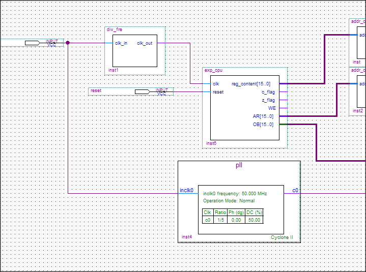
(1)开发板上的时钟是50MHz,经过50M的分频,实际输送给CPU的主频才1Hz。设置如此低的频率,目的是为了有足够的时间观察每一条指令的执行效果。
(2)PLL分频后的时钟10MHz送给了ROM,因为ROM也需要时钟线。本实验用ROM代替了RAM(HM6116),显然缺失了写的功能。为了让该ROM的操作如同可读静态RAM(HM6116)一样,用10MHz的时钟。可以看到,只要给ROM发送地址,ROM马上就把相应的数据发送出来。

(1)给ROM加一个16位地址变换为8位地址的目的是,本实验不需要用那么大的存储器,所以讲容量调整的小一点。
(2)本实验的输出寄存器直接是R0的内容,这一点在之前也有提到。由于实验板上只有8位led,所以执行指令的功能也只是改变R0的低8位。所以,高8位没必要保留,就通过加上一个地址变换器滤除无用的高8位。
(2)实验CPU程序
ROM存储器中的数据

翻译成指令:
movrd r0,#2
movrd r0,#8
movrd r0,#6
(3)实验效果
1、可以看到CPU如预期那样每3s(1条指令3个时钟周期),灯变换一次(执行一条指令)
2、灯按照预先设定的数据那样点亮。
(4)调试过程
本来暑假做实验时,用书上的程序编译后是能运行的。但是,春节后对学习过程进行整理过程中,发现书上的例程在quartus9.1版本编译后不能运行。经检测,问题出在节拍控制上(t1、t2、t3)。需要修改instruction_fetch文件中相应的程序才能成功运行。
4、实验结论
(1)CPU就是用数字电路搭建起来的
(2)CPU的基本结构是很简单的
参考:《开放式实验CPU设计》