ARVE:车辆到边缘网中的增强现实应用
本文为SIGCOMM 2018 Workshop (Mobile Edge Communications, MECOMM)论文。
笔者翻译了该论文。由于时间仓促,且笔者英文能力有限,错误之处在所难免;欢迎读者批评指正。
本文及翻译版本仅用于学习使用。如果有任何不当,请联系笔者删除。
本文作者包含4位,Pengyuan Zhou@University of Helsinki, Finland;Wenxiao Zhang@Hong Kong University of Science and Technology, Hong Kong; Tristan Braud@Hong Kong University of Science and Technology, Hong Kong; Pan Hui@Hong Kong University of Science and Technology, Hong Kong; Jussi Kangasharju@University of Helsinki, Finland
ABSTRACT (摘要)
Vehicular communication applications, be it for driver-assisting augmented reality systems or fully driverless vehicles, require an efficient communication infrastructure for timely information delivery. Centralized, cloud-based infrastructures present latencies too high to satisfy the requirements of emergency information processing and transmission. In this paper, we present a novel Vehicle-to-Edge (ARVE) infrastructure, with computational units co-located with the base stations and aggregation points. Embedding computation at the edge of the network allows to reduce the overall latency compared to vehicle-to-cloud and signifcantly trim the complexity of vehicle-to-vehicle communication. To demonstrate the efficiency of our solution, we apply these principles on an augmented reality head-up display. In this use case, vehicular communication is exploited to connect vehicle’s vision, and quickly propagate emergency information. ARVE is a general system framework, applicable to many practical scenarios. Our preliminary evaluation shows that ARVE noticeably decreases transmission latency with reasonable capital expenditure.
无论是驾驶辅助增强现实系统还是完全无人驾驶车辆,车辆通信应用都需要有效的通信基础设施来及时传递信息。集中式、基于云的基础设施存在过高的延迟,无法满足紧急信息处理和传输的要求。在本文中,我们提出了一种新颖的车辆到边缘(ARVE)基础设施,其计算单元与基站和聚合点共存。与车辆到云相比,在网络边缘嵌入计算允许减少总体延迟并且显着地减少车辆到车辆通信的复杂性。为了展示我们解决方案的效率,我们将这些原则应用于增强现实汽车平视显示器。在该用例中,利用车辆通信来连接车辆的视觉,并快速传播紧急信息。 ARVE是一个通用的系统框架,适用于许多实际场景。我们的初步评估表明,ARVE通过合理的资本支出显着降低了传输延迟。
1 INTRODUCTION (引言)
Connected automated driving has recently become closer to being a reality. In 2018, California and Shanghai authorized the deployment of autonomous vehicles on public roads for testing purposes [3, 21]. Vehicular communication systems play a key role in sharing information between vehicles and roadside infrastructure units (RSU) . Use cases include emergency warning system for vehicles, cooperative adaptive cruise control, collision warning etc. Current solutions focus on three types of communication: vehicleto-vehicle (V2V), vehicle-to-cloud (V2C), and vehicle-to-roadside infrastructure (V2I) [8, 10]. Although these solutions fulfll basic demands, efficiently sharing complex and large volumes of data among vehicles at scale remains a challenge.
最近,连接自动驾驶变得更加接近现实。 2018年,加利福尼亚和上海授权在公路上部署自动驾驶汽车进行试验[3,21]。 车辆通信系统在车辆和路边基础设施单元(RSU)之间共享信息方面起着关键作用。 用例包括车辆紧急警告系统,协同自适应巡航控制,碰撞警告等。目前的解决方案集中在三种类型的通信:车辆到车辆(V2V),车辆到云(V2C)和车辆到路边基础设施 (V2I)[8,10]。 虽然这些解决方案满足了基本需求,但是在大规模车辆之间有效地共享复杂和大量的数据仍然是一个挑战。
Figure 1 illustrates two related scenarios: (1) The leading truck encounters an unexpected pothole. The truck notifes the following cars to avoid a potential accident. (2) Congested traffic is out of sight for cars planning to take the road on the right. Once aware, these cars will choose a better path. In V2C, even though the leading truck immediately uploads the captured pothole information, the combined latency of transmission, processing and distribution may be too high for the following vehicles to avoid it. Similarly, the connection establishment time of V2V communication with the complexity of forwarding information in a constantly varying crowd of nodes can lead to vehicles having only partial knowledge of the situation. V2I provides better data distribution; however, sharing accurate emergency information entails nontrivial computation and coordination. Roadside infrastructures should therefore integrate computing features for fast and reliable emergency information propagation.
图1描述了两个相关场景:(1)领头的卡车遇到意外的坑洞。 卡车通知后续车辆以避免潜在的事故。(2)对于计划在右侧行驶的汽车而言,拥挤的交通是不可见的。 一旦意识到拥挤,这些汽车将选择更好的路径。 在V2C中,即使领头的卡车立即上传捕获的坑洞信息,传输、处理和分发的组合延迟对于后续车辆来说也可能太高从而无法避免。 类似地,V2V通信的连接建立时间与在不断变化的节点群中转发信息的复杂性可导致车辆仅具有对情况的部分了解。 V2I提供更好的数据分发; 然而,共享准确的紧急信息需要非凡的计算和协调。 因此,路边基础设施应集成计算功能,以实现快速可靠的紧急信息传播。
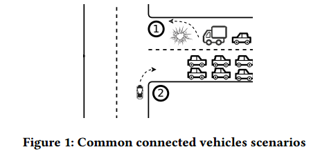
图1: 常见车辆连接场景
Edge computing facilitates latency-sensitive workloads by performing data processing in Edge Servers (ESes) located close to the user. The gain in latency provided by edge computing can be considerable. In Table 1, we measured the round trip latency for various servers through an LTE network: the first pingable IP, noted as Edge, a cloud server located in the same city and another server 1000 km away. Unsurprisingly, the latency to the closest server is half the round trip time to the furthest cloud server. Moreover, the ES presents a 20% improvement compared to the nearest cloud server, making it an attractive location for latency-sensitive applications.
边缘计算通过在靠近用户的边缘服务器(ESes)中执行数据处理来推进延迟敏感的工作负载。边缘计算提供的延迟增益可能相当大。 表1中,我们通过LTE网络测量了各种服务器的往返延迟:第一个可ping的IP(标记为Edge)、位于同一城市的云服务器和1000公里外的另一个服务器。 不出所料,到最近服务器的延迟是到最远的云服务器的往返时间的一半。 此外,与最近的云服务器相比,边缘服务器提高了20%,使其成为延迟敏感的应用程序的有吸引力的位置。

表1:通过LTE到不同目标的平均网络往返延迟。
We propose to use vehicle-to-edge (V2E) to enhance vehicular communications. Our design, ARVE, is a framework designed to be independent of the actual protocols, in order to allow it to apply equally to current as well as future networks. We choose to apply those principle to Connected Vehicle Views (CVV), a concrete use case of ARVE (see Section 3 for a detailed discussion of this use case) .
我们提出使用车辆到边缘(V2E)网络来增强车辆通信。 我们设计的ARVE是一个独立于实际协议的框架,使其能够同等地应用于当前和未来的网络。 我们选择将这些原则应用于连通车辆视图(CVV),这是ARVE的具体用例(有关此用例的详细讨论,请参阅第3节)。
Our contribution is threefold:
我们的贡献有三个:
- We present the design of ARVE, which equips RSUs with computation and cache capacity.
- 我们介绍了ARVE的设计,它为RSU(路边基础设施单元)配备了计算和缓存容量。
- Concrete application of ARVE to CVV using Augmented Reality Head-up Display (ARHUD). This use case displays the advantages of ARVE while scaling the problem of vehicle vision from a network perspective.
- ARVE在CVV中的具体应用,采用增强现实汽车平视显示器(ARHUD)。 该用例展示了ARVE的优势,同时从网络角度扩展了车辆视觉问题。
- We present a preliminary evaluation to show that ARVE offers noticeable performance improvements with reasonable expenditure in infrastructure.
- 我们给出初步评估,以表明ARVE在基础设施方面的合理支出的情形下提供了显着的性能改进。
The rest of paper is structured as follows. After a review of related work in section 2, we introduce the ARHUD use case in section 3. We then describe the system design, implementation and communication process of ARVE in section 4. The potential network protocols are discussed in section 5. Preliminary evaluation results are given in section 6. We conclude the paper in section 7.
论文剩余部分的结构如下。 在第2节回顾相关工作之后,我们在第3节介绍了ARHUD用例。然后在第4节中描述ARVE的系统设计,实现和通信过程。潜在的网络协议将在第5节中讨论。初步评估结果在第6节中给出。我们在第7节中总结了这篇论文。
3 USE CASE: CONNECTED ARHUD (用例:连通ARHUD)
One of the main concerns in the automotive world is safety. According to the 2015 National Motor Vehicle Crash Causation Survey by National Highway Traffic Safety Administration (NHTSA), 93% of crashes are attributed to drivers, of which, around 74% are due to erroneous recognition or decision [20]. However, autonomous vehicles can also get “confused” easily. For instance, GM Cruise autonomous cars sometimes slow down or stop if they see a bush on the roadside [13] and similar issues exist in lane changes. As such, the intervention of a human driver is still critical for safety. To assist the driver, vehicles are outftted with sensors and display devices which provide valuable information to the driver, such as about environmental condition and the driver’s driving habits. The most common display method is a heads-up-display (HUD).
汽车领域的主要关注点之一是安全性。根据美国国家公路交通安全管理局(NHTSA)2015年全国机动车碰撞原因调查,93%的车祸归因于司机,其中约74%是由于错误的认可或决定造成的[20]。 然而,自动驾驶汽车也容易“混淆”。例如,如果通用机器的Cruise自动驾驶汽车在路边看到灌木丛时,它们有时会减速或停止[13],并且在车道变换中存在类似的问题。 因此,人类驾驶员的干预对于安全仍然至关重要。 为了帮助驾驶员,车辆配备有传感器和显示装置,其向驾驶员提供有价值的信息,例如关于环境条件和驾驶员的驾驶习惯的信息。 最常见的显示方法是汽车平视显示器(HUD)。
In recent years, augmented-reality (AR) HUDs have attracted both academic and industrial attention [14, 22]. AR can embed 3-D views of the information into the rendering background on the HUD, enabling accurate obstacle recognition and emergency notifcation. Previous work has put effort on matching the embedded information with the real environment, cognitive usability, visibility, among others [17, 18]. However, connecting vehicle views via ARHUD remains a challenge. Recently, the authors in [19] explored how to share vision between two vehicles. Although the work proposed solutions for basic view transformation, it is still not enough to connect vehicle vision at scale under realistic concerns of bandwidth, latency and computational resources.
近年来,增强现实(AR)HUD吸引了学术和工业界的关注[14,22]。 AR可以将信息的三维视图嵌入到HUD上的渲染背景中,从而实现准确的障碍识别和紧急通知。以前的工作已经将嵌入信息与真实环境、感知可用性和可见性等相匹配[17,18]。 但是,通过AR HUD连接车辆视图仍然是一个挑战。 最近,文献[19]的作者探讨了如何在两辆车之间共享视觉。 尽管该工作提出了基本视图转换的解决方案,但在带宽,延迟和计算资源的现实考虑下,仍然不足以大规模地连接车辆视觉。
Challenges are multiple: (1) A crowd-sourced map which is the combined 3D point cloud from the independent real-time views of the connected vehicles, acts as a reference coordinate system to localize incidents. This map is too voluminous for both real time generation and transmission, hence we need to develop additional mechanisms to address its proper generation and maintenance. (2) Proper network protocol stack needs to be explored. There are several protocols proposed and tested in vehicular network. An integrate protocol stack fit for different applications is still beingless. (3) Privacy and security concerns may arise in distributed V2V communications.
挑战是多方面的:(1)众包地图(来自连通车辆的独立实时视图的组合3D点云)充当参考坐标系统来定位事故。 这张地图对于实时生成和传输而言太过庞大,因此我们需要开发其他机制来解决其正确生成和维护问题。(2)需要探索适当的网络协议栈。 在车载网络中提出并测试了多种协议。 针对不同应用程序的集成协议栈仍然无法实现。(3)分布式V2V通信中可能出现隐私和安全问题。
In this paper, we design ARVE, a framework designed to enable Connected Vehicle Views (CVV) where nearby vehicles are able to share their views, assisted by the edge components, and form a more holistic view of their current situation. This enables fast distribution of critical information, i.e., obstacle detection, emergency report and collision notifcation. While we use CVV as an example, ARVE can serve any similar application, which requires computation and short latency.
在本文中,我们设计了ARVE,这是一个旨在实现连通车辆视图(CVV)的框架,其中附近的车辆能够在边缘组件的帮助下分享他们的视图,并形成对其当前情况的更全面的视图。 这使得能够快速分发关键信息,即障碍物检测,紧急报告和碰撞通知。 虽然我们使用CVV作为示例,ARVE可以为任何类似的应用程序(需要计算和短延迟)提供服务。
4 SYSTEM DESIGN (系统设计)
In this section, we describe the ARVE design. First, we explain our system architecture and describe the major communication processes in the system. Then, we propose an implementation scheme and present how to apply it to CVV.
在本节中,我们将介绍ARVE设计。 首先,我们解释我们的系统架构并描述系统中的主要通信过程。 然后,我们提出了一个实现方案,并介绍了如何将其应用于CVV。
4.1 System Architecture (系统架构)
We now introduce the ARVE architecture model. It has three key elements: environment, vehicles and edge servers. Environment includes the background road network, roadside buildings, infrastructures and pedestrians, etc., while the others represent the computational elements in the system. Figure 2 depicts our system architecture in which ESes are distributed hierarchically in two tiers. Some are co-located with base stations, while others are colocated with aggregation points. We name the former Tier1 Edge Server (T1 ES) and the latter are Tier2 Edge Servers (T2 ES) .
现在,我们介绍ARVE架构模型。它包含三个关键要素:环境、车辆和边缘服务器。 环境包括背景道路网络、路边建筑物、基础设施和行人等,而其它代表系统中的计算元素。 图2描绘了我们的系统架构,其中边缘服务器(ESes)分布在两层中: 一些与基站共存,而另一些则与聚合点共存。 我们将前者称为Tier1-边缘服务器(T1 ES),后者命名为Tier-2边缘服务器(T2 ES)。
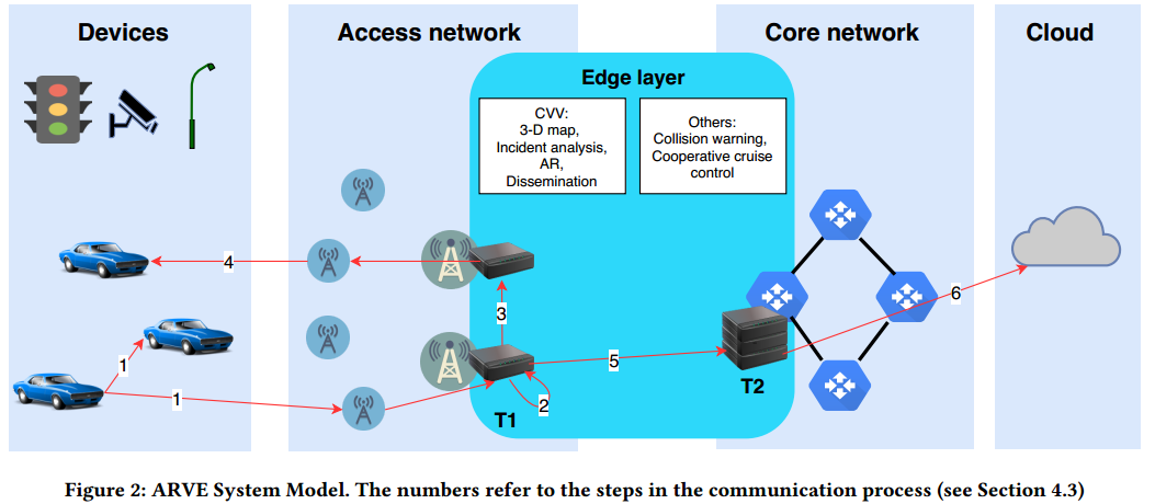
图2: ARVE系统模型。数字表示通信过程中的步骤(见4.3节)。
The edge layer is the amalgamation of T1 and T2 ESes and is where ARVE operates. Edge layer communicates with vehicles and RSUs via nearby radio access network, and transmits data with remote cloud for synchronization. Each T1 ES has a range over the area covered by its connected macrocell and surrounded small cells. The hierarchical design of the edge layer allows applications with different requirements to be processed differently for better performance. T2 ES collects data from multiple areas (multiple T1 ESes) to provide larger scale of service and data backup, e.g., to improve traffic flow by sending cruise control messages. T1 ES, which is closer to vehicles, serves applications with higher latency sensitivity, e.g., emergency notifcations.
边缘层是T1和T2 ESes的融合,是ARVE运行的地方。边缘层通过附近的无线接入网络与车辆和RSU通信,并通过远程云传输数据以进行同步。 每个T1 ES的范围均超过其连接的宏单元和周围小单元所覆盖的区域。 边缘层的分层设计允许对具有不同要求的应用进行处理,以获得更好的性能。 T2 ES从多个区域(多个T1 ES)收集数据以提供更大规模的服务和数据备份,例如,通过发送巡航控制消息来改善流量流。 更靠近车辆的T1 ES服务于具有更高等待时间敏感性的应用,例如紧急通知。
4.2 ARVE Basic Operation (ARVE基本操作)
The basic operation of ARVE relies on the generation of a map around the vehicle, to enable awareness of the surroundings. The generation of the crowd-sourced map involves multiple steps. First, for each vehicle, we generate a 3D point cloud of the road in front of the vehicle using visual sensors present in the vehicle (e.g., LiDAR, RGBD camera). Then, the point clouds from multiple connected vehicles are transmitted to the edge server and combined into a 3D street view. Finally, the combined point cloud of the street is transmitted back to the vehicles, and each vehicle can display the street view according to its own position, so that the driver would be able to see the extended view of the whole street on the HUD.
ARVE的基本操作依赖于生成车辆周围的地图,以使人们能够意识到周围环境。 众包地图的生成涉及多个步骤。 首先,对于每个车辆,我们使用车辆中存在的视觉传感器(例如,LiDAR,RGBD相机)生成车辆前方道路的3D点云。 然后,来自多个连接车辆的点云被传输到边缘服务器并组合成3D街道视图。 最后,街道的组合点云被传输回车辆,并且每辆车可以根据其自身位置显示街景,使得驾驶员能够在HUD上看到整个街道的扩展视图。
4.3 Communication Process (通信进程)
Next we describe the six basic steps (marked in Figure 2) in ARVE: neighbor notifcation, data processing, transmission, dissemination, aggregation, and upload. The exact details depend on the actual application; here we use an emergency notifcation application to showcase the communication process:
接下来我们介绍ARVE中的6个基本步骤(图2中标记):邻居通知、数据处理、传输、传播、聚合和上传。详细的细节依赖于真实应用;这里,我们使用紧急通知应用的展示通信进程:
- Neighbor notifcation: The nearest vehicles require the fastest notifcation of emergencies. Therefore, upon emergency detection, a vehicle needs to warn its neighbor vehicles immediately, by sending simple notifcation via V2V. The notifcation includes only critical messages, e.g., name/type and coordinates of the emergency, to minimize V2V bandwidth usage and latency. The V2V notifcation is relayed until reaching a predefined maximum number of hops. Meanwhile, the vehicle sends a detailed report to nearest T1 ES via V2I. The report includes collected sensor and camera data with only the minimal, necessary data compression.
- 邻居通知:最近的车辆需要最快的紧急通知。 因此,在紧急检测时,车辆需要通过V2V发送简单的通知来立即警告其邻近车辆。 该通知仅包括关键消息,例如,紧急情况的名称/类型和坐标,以最小化V2V带宽使用和等待延迟。 V2V通知被中继,直到达到预定义的最大跳数。 同时,车辆通过V2I向最近的T1 ES发送详细报告。 该报告包括收集的传感器和摄像机数据,只有最小的必要数据压缩。
- Data processing: Once a T1 ES receives a report, it processes the data and caches it for passing on to later passing vehicles. As discussed in [19], sharing views of incidents among vehicles is nontrivial. ESes maintain and update local map in real time, by collecting data from passing vehicles and synchronize it with a cloud data center. With the up-to-date map, T1 ESes serve as calibration points which map the reported incident onto absolute coordinates and notify nearby vehicles more efciently.
- 数据处理:一旦T1 ES收到报告,它就会处理数据并对其进行缓存,以便传递给后来过往的车辆。 正如[19]中所讨论的那样,共享车辆事故的视图是非凡的。 通过从过往车辆收集数据并将其与云数据中心同步,ES实时维护和更新本地地图。 利用最新的地图,T1 ESes可用作校准点,将报告的事件映射到绝对坐标上,并更有效地通知附近的车辆。
- Data transmission: The maintained map or other data, e.g., emergency or congestion information, can be transmitted between ESes via wired or wireless channels.
- 数据传输:维护的地图或其他数据,例如紧急或拥塞信息,可以通过有线或无线信道在ES之间传输。
- Data dissemination: Upon data updates, ESes disseminate data to vehicles in their coverage areas.
- 数据传播:在数据更新后,ESes将数据传播到其覆盖区域的车辆。
- Data aggregation: T1 ESes aggregate data before sending it to T2 ESes for applications requiring larger amounts of data (naturally assuming aggregation is acceptable for the application).
- 数据聚合:对需要大量数据的应用程序,T1 ESes在将数据发送到T2 ESes之前聚合数据(当然假设聚合对于应用程序是可接受的)。
- Data upload: T2 ESes synchronize with cloud to update data and enable synchronization across a larger geographical area.
- 数据上传:T2 ESes与云同步以更新数据并在更大的地理区域内实现同步。
This communication model has several important benefits, namely:
这一通信模型具有多个重要的好处,即:
- Neighbor notifcationcombines two methods of which the simple notifcation warns closest vehicles with the lowest delay, while the detailed report sends all information for ESes to generate AR data for CVV.
- 邻居通知结合了两种方法,其中简单通知警告最近的车辆因而具有最低延迟,而详细报告发送所有信息以使得ESes可以生成CVV的AR数据。
- Cache capacityof an ES noticeably improves the performance of vehicular communication system. A common scenario is that vehicle detects an anomaly on road without nearby vehicles. The vehicle therefore cannot pass on the notifcation to other vehicles, but instead must upload it into the cloud. However, for a later vehicle to receive the notifcation in a timely manner, it needs to get the data all the way from cloud, or be in the coverage area of nearby RSUs when the data is still in transmission. ESes change this shortcoming by caching the data and broadcasting within predefned period, so that later vehicles receive the notifcation with lower latency.
- ES的高速缓存容量显着提高了车载通信系统的性能。 常见的情况是车辆在没有附近车辆的情况下检测到道路上的异常。 因此,车辆不能将通知传递给其他车辆,而是必须将其上传到云中。 然而,对于后来的车辆及时接收通知,它需要从云端获取数据,或者当数据仍在传输时位于附近RSU的覆盖区域。 ESes通过在预定时间段内缓存数据和广播来改变这一缺点,以便后来的车辆接收具有较低延迟的通知。
- Hierarchical edgeenables efcient handling of workloads with different requirement by processing the data at the different tiers, depending on the application requirements.
- 通过根据应用程序要求处理不同层的数据,分层边缘可以根据不同的要求有效地处理工作负载。
4.4 Implementation (实现)
In terms of implementation, two key issues arise: the deployment and placement of ESes. Deployment refers to the internal implementation of an ES while placement refers to the physical placement of the ES.
在实现方面,出现了两个关键问题:ES的部署和放置。 部署是指ES的内部实现,而放置是指ES的物理位置。
Deployment: Our proposal to co-locate ESes with base stations and aggregation points are motivated by existing trends. The MEC standard developed by European Telecommunications Standards Institute (ETSI) proposes to deploy servers at the cellular base station to serve local mobile subscribers with fast response times [4]. Colocation with existing infrastructure also achieves cost-efciency. For these reasons, T1 ESes co-located with base stations is a straightforward solution. Next, we need to take a look at cellular network deployment in near future to understand the rationale of T1 ES deployment. According to the 2017 survey of Small Cell Forum (SCF), by 2025, new non-residential small cell deployments will reach almost 8.5 million, which is 22 times higher than in 2015 [9]. On the other hand, 5G will also accelerate the deployment of small cells. 58% of the operators, according to the same survey of SCF, expect to focus primarily on small cells in the frst 2-3 years of deploying 5G. However, the number of macrocell seems to grow much slower. According to Nokia, trafc density of a very busy US city increased fourfold from 2004 to 2014, yet the average density of macrocell sites did not change [5]. We conjecture that small cell deployment will increase much faster than macrocell deployment in the near future. As a result, capacities of T1 ESes are facing increasing challenges and therefore we propose to locate the T2 ESes at a higher layer in the network to enable more efcient aggregation and backup.
部署:我们将ES与基站和聚合点共同放置的方案受到现有趋势的推动。由欧洲电信标准协会(ETSI)开发的MEC标准建议在蜂窝基站部署服务器,以便为本地移动用户提供快速的响应时间[4]。与现有基础设施的共置也可以实现成本效益。由于这些原因,T1 ESes与基站位于同一位置是一个简单的解决方案。接下来,我们需要了解不久的将来的蜂窝网络部署,以了解T1 ES部署的基本原理。根据2017年小型蜂窝论坛(SCF)的调查,到2025年,新的非住宅小型蜂窝部署将达到近850万,比2015年高出22倍[9]。另一方面,5G也将加速小型蜂窝的部署。根据对SCF的同一调查,58%的运营商预计在部署5G的前2 - 3年内主要关注小型蜂窝。但是,宏蜂窝的数量似乎增长得慢得多。据诺基亚称,美国一个非常繁忙的城市的交通密度从2004年到2014年增长了四倍,但宏蜂窝站点的平均密度没有变化[5]。我们推测,在不久的将来,小蜂窝部署的增长速度将远远快于宏蜂窝部署。因此,T1 ES的容量面临越来越多的挑战,因此我们建议将T2 ESes定位在网络的更高层,以实现更高效的聚合和备份。
Placement: To avoid unnecessary investment and complexity, the ESes location should be carefully determined. While T2 ESes are locate typically at aggregation points, which are relatively few in number, locations of T1 ESes have much more candidates, namely the macrocells. Cities like New York have macrocell deployments with 500 m inter-site distance or less [6]. Deploying one T1 ES per macrocell would be excessive in terms of investment, so to improve efciency, we need to optimize the selection of locations in some manner. Our proposed algorithm includes two steps, namely average traffic clustering and edge capacity assignment. We opt for a hierarchical clustering algorithm since our edge layer already is constructed hierarchically. Edge capacity assignment is solved as a primary facility location problem, where we simply assign edge capacity to each cluster center (both Tier 1 and 2), proportional to its average traffic. The order of edge capacity is calculated through edge server capacity, trafc density, and resource consumption of the application (section 6).
放置:为避免不必要的投资和复杂性,应仔细确定ESes的位置。虽然T2 ESes通常位于聚合点,其数量相对较少,但是T1 ESes的位置具有更多的候选者,即宏蜂窝。纽约等城市的宏蜂窝部署距离为500米或更短[6]。在每个宏蜂窝中部署一个T1 ES在投资方面会过多,因此为了提高效率,我们需要以某种方式优化位置选择。我们提出的算法包括两个步骤,即平均交通量聚类和边缘容量分配。我们选择层次聚类算法,因为我们的边缘层已经是分层构造的。边缘容量分配作为主要设施位置问题得到解决,我们只需为每个集群中心(第1层和第2层)分配边缘容量,与其平均交通成比例。边缘容量的顺序是通过边缘服务器容量、流量密度和应用程序的资源消耗来计算的(第6节)。
4.5 Use case solution Overview (用例解决方案概览)
Now we describe how to implement an ARHUD-based CVV. To solve the challenges described in section 3, we need to implement the following components: (1) Map maintenance: Vehicles record the surrounding 3-D features with the coordinates of traversed streets and send to nearest T1 ESes. T1 ESes stitch together the collected segments to form 3-D neighborhood maps. (2) Incident report: Once a vehicle detects an incident, it sends the simple notifcation and detailed report to the nearest vehicle and T1 ES, respectively. (3) Data process: The ES extracts the data from the received report and localizes the incident in the map it maintains. The localization can use either the received coordinates or map the observed 3-D features within the map. (4) Transmission and dissemination: Meanwhile, the ES forwards the notifcation to nearby T1 ESes (directly or via T2 ES) and disseminates to vehicles within its coverage. The range of the dissemination area depends on the magnitude of the incident and the coverage area of the ES. (5) Aggregation: T2 ES aggregates data from T1 ESes to gather information of larger area. Use cases include, for example, crowd–sourcing the neighborhood maps to build an urban 3-D map or trafc light control. (6) Synchronization: ESes synchronize with the cloud periodically or when triggered by specifed incidents.
现在,我们描述如何实现基于ARHUD的CVV。为了解决第3节中描述的挑战,我们需要实现以下组件:(1)地图维护:车辆使用经过的街道的坐标记录周围的3-D特征并发送到最近的T1 ES。 T1 ES将收集的段拼接在一起,形成3-D邻域地图。(2)事故报告:一旦车辆发现事故,它会将简单的通知和详细报告分别发送到最近的车辆和T1 ES。(3)数据处理:ES从接收到的报告中提取数据,并将在它维护的地图中定位事件。定位可以使用接收的坐标或映射地图中观察到的3-D特征。(4)传输和传播:同时,ES将通知转发到附近的T1 ES(直接或通过T2 ES)并传播到其覆盖范围内的车辆。传播区域的范围取决于事件的严重程度和ES的覆盖范围。 (5)聚合:T2 ES聚合来自T1 ES的数据以收集更大区域的信息。例如,用例包括众包邻域地图以构建城市3-D地图或交通灯控制。 (6)同步:ESes定期与云同步,或者由指定的事件触发。
5 NETWORK ISSUES (网络问题)
In this section, we discuss possible network protocols for V2E powered vehicle communication system. ARVE does not have any specifc requirements on the networking technologies or protocols that are used. We can accommodate different technologies including cellular, Wi-Fi, D2D and DSRC so that they complement each other to fulfll different kinds of workloads and constitute an integrated networking system. Considering Figure 2 as an example, the device layer includes V2V and V2I communication where DSRC and D2D protocols coexist to provide better performance. Stand-alone D2D (Wi-Fi Direct) and DSRC could support V2V in scenarios even without network coverage. Another D2D protocol, LTE Direct, needs network assist and supports long distance connection. As shown in [19], Wi-Fi Direct has better performance than LTE and higher theoretical throughput than DSRC. However, WLAN chipsets are unlikely to fulfill ad-hoc communication at high speeds which makes them unreliable for vehicle network [7]. Here we propose to use a combination of D2D and DSRC to serve large volumes of data and fast data transmission, respectively. For instance, in our communication process, vehicle sends out the simple notifcation to closest vehicle by DSRC, while sending the detailed report to nearby ES by D2D. The rest of the system communicates via wired and LTE or 5G network. Today’s cell phone connects to internet via cellular or Wi-Fi network, depending on local network coverage and subscription etc. Likewise, vehicular networks should also use multiple complementary protocols to function in different scenarios.
在本节中,我们将讨论V2E增强的车辆通信系统的可能网络协议。 ARVE对所使用的网络技术或协议没有任何特定要求。我们可以适应不同的技术,包括蜂窝、Wi-Fi、D2D和DSRC,以便它们相互补充满足不同类型的工作负载,并构成一个集成的网络系统。以图2为例,设备层包括V2V和V2I通信,其中DSRC和D2D协议共存以提供更好的性能。即使没有网络覆盖,独立的D2D(Wi-Fi Direct)和DSRC也可以支持V2V。另一种D2D协议(LTE Direct)需要网络辅助并支持长距离连接。如[19]所示,Wi-Fi Direct具有比LTE更好的性能和比DSRC更高的理论吞吐量。然而,WLAN芯片组不太可能在高速率下满足ad-hoc通信,这使得它们对车辆网络不可靠[7]。在这里,我们建议使用D2D和DSRC的组合来分别提供大量数据和快速数据传输。例如,在我们的通信过程中,车辆通过DSRC将简单通知发送到最近的车辆,同时通过D2D将详细报告发送到附近的ES。系统的其余部分通过有线和LTE或5G网络进行通信。今天的手机通过蜂窝或Wi-Fi网络连接到互联网,具体取决于本地网络覆盖和订阅等。同样,车载网络也应该使用多种互补协议在不同的场景中运行。
6 PRELIMINARY EVALUATION (初步评估)
In this section, we will present a primary ES placement solution for a CVV application based on ARVE and elaborate the system improvement over current vehicular network.
本节,我们将为基于ARVE的CVV应用提供主要的ES放置解决方案,并详细说明对当前车载网络的系统改进。
Data Collection and Analysis: To address the edge server placement problem, we study the base station and traffic distribution pattern in the center area of London as an example. The selected area has a size of 26km * 20km, and we collect the LTE base station location data and traffic volume data that fall into this area according to GPS coordinates.
数据收集和分析:为了解决边缘服务器放置问题,我们以伦敦中心区域的基站和交通分布模式为例进行研究。 所选区域的大小为26km*20km,我们根据GPS坐标收集落入该区域的LTE基站位置数据和交通量数据。
First we cluster the traffic volume data according to their GPS coordinates, and divide the selected area into 20 small areas according to the clustering result. The traffic distribution and area partition results are shown in Figure 3, where each colored dot represents the location of the aggregated traffic, and the different sizes of the dots reflect the different traffic volumes in 12 hours during daytime.
首先,我们根据其GPS坐标对交通量数据进行聚类,并根据聚类结果将所选区域划分为20个小区域。 交通分布和区域划分结果如图3所示,其中每个彩色圆点代表聚合交通的位置,不同尺寸的点反映出不同的交通量(白天12个小时)。
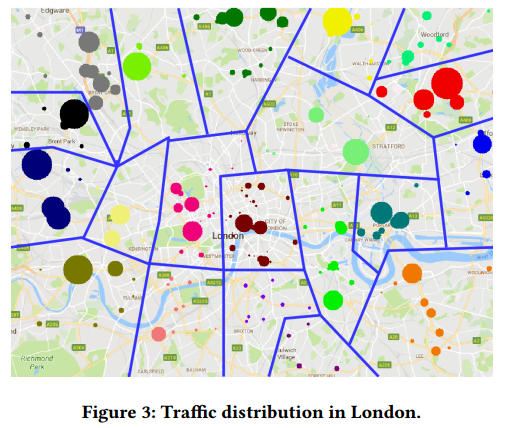
图3:伦敦交通分布
Next we want to see if base stations distribute differently from traffic, to understand if this would influence our co-located ES placement. There are 22041 LTE base stations located within this area, among which 1538 base stations have a coverage radius larger than 3000m, comparable to macrocell. We plot these 1538 base stations on the map, as shown in Figure 4. It can be easily observed that the base stations distribute evenly and reasonably match the amount of traffic in dense areas. As a result, using base stations as deployment points is not going to deviate the ES placement from the actual traffic patterns.
接下来,我们想看看基站分布和交通量是否不同,以了解这是否会影响共存ES的位置。 该区域内有22041个LTE基站,其中1538个基站的覆盖半径大于3000m,与宏蜂窝相当。 我们在地图上绘制了这1538个基站,如图4所示。可以很容易地观察到基站分布均匀且合理地匹配密集区域中的交通量。 因此,使用基站作为部署点不会使ES布局偏离实际的交通模式。

图4:伦敦选定区域的LTE基站(覆盖半径大于3000米)分布
Edge Server Placement: H. Qiu et al. reported a typical Augmented Vehicle Reality system [19], where the AR related processing (e.g., point cloud manipulation) takes 1.337 sec on average. Considering this processing as the AR workload of the edge servers, one edge server is able to handle 2692 requests per hour, that is, serving around 32k vehicles during each daytime.
边缘服务器放置:H. Qiu等报告了一种典型的增强型车辆现实系统[19],其中AR相关处理(例如,点云操纵)平均需要1.337秒。 将此处理视为边缘服务器的AR工作负载,一台边缘服务器每小时能够处理2692个请求,即每天服务大约32,000个车辆。
The edge server placement is correlated with the traffic volume distribution, which is not uniform among the 20 small areas. The numbers of edge servers needed by each area are shown in Figure 5. In total 90 edge servers are needed in the selected center area of London and the largest clusters of ESes have a total of 8 ESes, while the bulk of them contain 3–4 ESes.
边缘服务器放置与交通量分布相关,这在20个小区域中不均匀。 每个区域所需的边缘服务器数量如图5所示。在伦敦选定的中心区域共需要90个边缘服务器,最大的ESes集群总共有8个ES,而其中大部分包含3-4个ESes。

图5:不同区域需要的边缘服务器的数量
Latency Comparison between Edge Server and Cloud Server. Edge servers bring the processing capability to the vicinity of vehicles. The latency of augmented vehicle reality consists of mainly two parts: the data transmission time and the server processing time. The data processing time taken by the edge server and the cloud server would not differ signifcantly, but the data transmission time is greatly influenced by the transmission distance.
边缘服务器和云服务器之间的延迟比较。边缘服务器将处理能力带到车辆附近。增强车辆现实的延迟主要包括两部分:数据传输时间和服务器处理时间。 边缘服务器和云服务器的数据处理的时间差异不大,但数据传输时间受传输距离的影响很大。
As reported in [19], the point cloud data size of the view generated by a 720P resolution stereo camera is 14.75 MB. Considering the edge server scenario, the uplink bandwidth between the vehicle and the LTE base station achieves on average 25 Mbps4, so that the transmission of the point cloud fnishes in 4.72 sec. On the other hand, the transmission between vehicles and cloud servers is obviously slower, as the data needs to traverse through the Internet. Taking Google Cloud Platform as an example, the average uplink bandwidth is 4.4 Mbps5, so that the transmission of the point cloud could take up to 26.82 sec.
如[19]中所报道的,720P分辨率立体相机生成的视图的点云数据大小为14.75 MB。 考虑到边缘服务器场景,车辆和LTE基站之间的上行链路带宽平均达到25Mbps,因此点云的传输在4.72秒内完成。 另一方面,车辆和云服务器之间的传输速度明显较慢,因为数据需要经互联网传输。 以Google Cloud Platform为例,平均上行带宽为4.4 Mbps,因此点云的传输可能需要26.82秒。
Our preliminary evaluation shows that ARVE would decrease transmission latency noticeably.
我们的初步评估表明ARVE可以显著降低传输延迟。