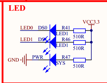
原理图:
MCU在开发板原理图的第二页,LED在开发板原理图的第三页
由图可知,PF9 ,PF10 若输出低电平则灯亮,高电平则灯灭

选推挽输出
代码步骤
-
使能IO口时钟。
调用函数RCC_AHB1PeriphClockCmd();不同的外设调用的时钟使能函数可能不一样 -
初始化IO口模式。调用函数GPIO_Init();
-
操作IO口,输出高低电平。
GPIO_SetBits();
GPIO_ResetBits();
实现步骤
1.删掉FWLIB中不用的源文件(以提高编译速度),保留misc,rcc , gpio , uart
2.新建hardward文件夹,其中新建led文件夹,其中新建led.c 和led.h,分别引入工程
3.led.h中:
#ifndef __LED_H
#define __LED_H
void LED_Init(void);
#endif
4.led.c中,每个函数用gotodefinition查看定义
怎么写函数里的参数呢?找到assert_param 函数
assert_param(IS_RCC_AHB1_CLOCK_PERIPH(RCC_AHB1Periph));
其中最里层的括号里会出现参数,外面用一个宏包着
对包着参数的那个宏,(如下面的IS_RCC_AHB1_CLOCK_PERIPH)goto definition,可以看到其定义
1)如果直接是A||B
例如
#define IS_FUNCTIONAL_STATE(STATE) (((STATE) ==DISABLE) || ((STATE) == ENABLE))
那么可选参数即为A和B
另一种情况:
2)如果不是那样,而是比较复杂,里面直接一些十六进制,就往它上面看,基本就是可选值
例如
#define IS_RCC_AHB1_CLOCK_PERIPH(PERIPH) ((((PERIPH) & 0x810BE800) == 0x00) && ((PERIPH) != 0x00))
如图这些define的内容就是该参数的可选项(从注释也可以看出)

完整代码
main.c
#include "stm32f4xx.h"
#include "led.h"
#include "delay.h"


int main(void)
{
	LED_Init();
	delay_init(168); //时钟为168M
	while(1){
		GPIO_ResetBits(GPIOF,GPIO_Pin_9|GPIO_Pin_10);
		delay_ms(500);
		GPIO_SetBits(GPIOF,GPIO_Pin_9|GPIO_Pin_10);
		delay_ms(500);
	}
}
led.c
#include "led.h"
#include "stm32f4xx.h"   //固件库
void LED_Init(void)
{
	GPIO_InitTypeDef GPIO_InitStructure;
	//1.使能gpio的时钟
	//FWLIB , stm32f4xx_rcc.h
	RCC_AHB1PeriphClockCmd(RCC_AHB1Periph_GPIOF,ENABLE);   //时钟使能函数
	//2.GPIO初始化
	GPIO_InitStructure.GPIO_Pin=GPIO_Pin_9|GPIO_Pin_10;
	GPIO_InitStructure.GPIO_Mode=GPIO_Mode_OUT;
	GPIO_InitStructure.GPIO_OType=GPIO_OType_PP;//推挽输出(强高低电平)
	GPIO_InitStructure.GPIO_PuPd=GPIO_PuPd_UP;//上拉 (默认情况下高电平,led不亮)
	GPIO_InitStructure.GPIO_Speed=GPIO_Speed_50MHz;
	GPIO_Init(GPIOF,&GPIO_InitStructure);
	//3.置为高电平(默认不亮)
	GPIO_SetBits(GPIOF,GPIO_Pin_9|GPIO_Pin_10);
led.h
#ifndef __LED_H
#define __LED_H
void LED_Init(void);
#endif