一设计功能
通过串口发送端,可以发送一字节的数据。有输入标志信号和发送完成的标志信号进行控制发送过程,核心是发送的时序图。串口发送分成两个部分:串口波特率和串口数据发送。即空闲时的高电平和起始位,八位数据位,停止位。
二设计输入
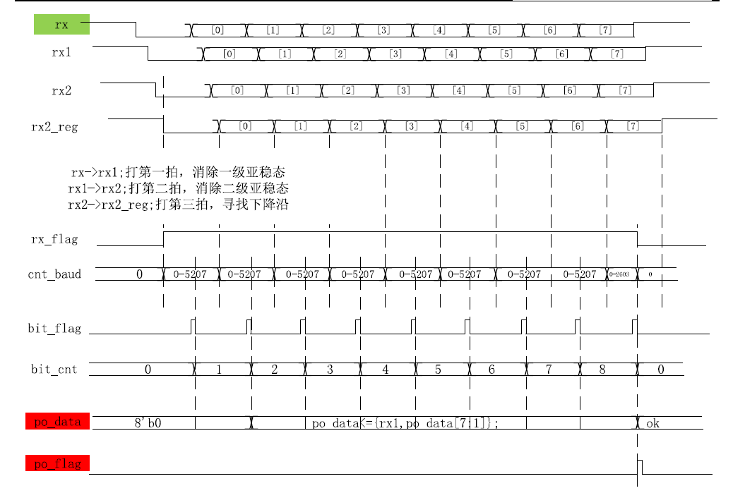
下面的程序代码是从上到下,从最基本的时钟开始,分频计数器,分频标志信号,波特率,数据位,和输出数据信号,输出标志信号。
|
module uart_tx
(
input wire sclk,
input wire s_rst_n,
input wire [7:0]pi_data,
input wire pi_flag,
output reg tx
);
reg [3:0]bit_cnt;
reg bit_flag;
//data reg
reg [7:0]data_reg;
always@(posedge sclk or negedge s_rst_n)
if(s_rst_n==0)
data_reg<=8'b0;
else if(pi_data)
data_reg<=pi_data;
else begin
data_reg<=data_reg;
end
//tx_flag
reg tx_flag;
always@(posedge sclk or negedge s_rst_n)
if(s_rst_n==0)
tx_flag <= 0;
else if(pi_flag)
tx_flag<=1;
else if(bit_cnt==4'd8 & bit_flag)
tx_flag<=0;
else begin
tx_flag<=tx_flag;
end
//baud counter
parameter cnt_MAX = 13'd5208;
reg [12:0]cnt_baud;
always@(posedge sclk or negedge s_rst_n)
if(!s_rst_n)
cnt_baud<=13'd0;
else if(cnt_baud==cnt_MAX)
cnt_baud<=13'd0;
else if(bit_cnt==4'd8 & bit_flag)
cnt_baud<=13'd0;
else if(tx_flag)
cnt_baud<=cnt_baud+1'b1;
//bit_flag
//波特率标志信号,每计数满一个波特率周期拉高
always@(posedge sclk or negedge s_rst_n)
if(s_rst_n==0)
bit_flag<=1'b0;
else if(cnt_baud==cnt_MAX)
bit_flag<=1'b1;
else begin
bit_flag<=0;
end
//bit_cnt
always@(posedge sclk or negedge s_rst_n)
if(s_rst_n==0)
bit_cnt<=4'd0;
else if(bit_cnt==4'd8 & bit_flag)
bit_cnt<=4'd0;
else if(bit_flag)
bit_cnt<=bit_cnt+1'b1;
always@(posedge sclk or negedge s_rst_n)
if(s_rst_n==0)
tx<=1'b1;
else begin
case(bit_cnt)
0:tx <=0;
1:tx <=data_reg[0];
2:tx <=data_reg[1];
3:tx <=data_reg[2];
4:tx <=data_reg[3];
5:tx <=data_reg[4];
6:tx <=data_reg[5];
7:tx <=data_reg[6];
8:tx <=data_reg[7];
default:tx <=1;
endcase
end
endmodule
|
根据发送时序图,写的串口发送模块。