一、什么事串口?
大家常说串口,其实串口有很多种UART,SPI,IIC都是串口,一般大家口中的串口就是UART(Universal Asynchronous Receiver/Transmitter),STM32上集成了UART的控制器,所以我们通过简单的配置就可以实现UART通信的功能。当然光有控制器可以在单板间通信,但大部分的应用场景都是需要远距离的抗干扰传输,这时就需要做电平转换,,目前工业上常用的串口屏,串口透传zigbee,诸如此类的设备都会用到标准的串行接口,所以单板上一般会加一个收发器,来实现电平转换,常用的串行接口就是大家常说的232,485,422等。
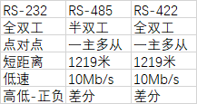
对于STM32来说不同的接口控制方法基本类似(就两线制来说),485会多一条读写的控制引脚,因为它是半双工,不能同时读写。
二、怎样使用它?
1.串口外设使能,GPIO使能
RCC_APB2PeriphClockCmd();
2.串口复位
USART_DeInit();
3.GPIO模式设置
GPIO_Init();
GPIO_PinAFConfig();
4.串口参数初始化
USART_Init();
5.开启中断并初始化NVIC
NVIC_Init();
USART_ITConfig();
6.使能串口
UART_Cmd();
7.编写中断处理函数
USARTx_IRQHandler();
8.串口数据收发
void USART_SendData();
u8 USART_ReceiveData();
贴一个配置代码
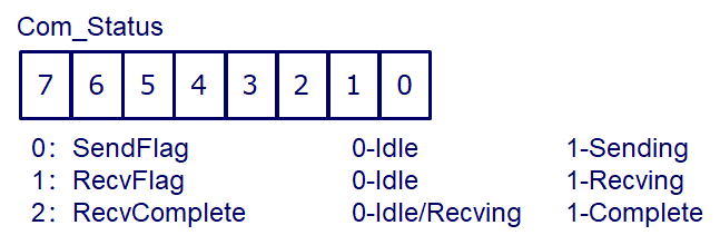
这是串口控制器结构体
typedef struct Com_Manager
{
	u8 Status;
	u8 Send_Buf[256];
	u16 TxByte_Counter;
	u16 Stop_Byte;
	u8 Recv_Buf[256];
	u16 RxByte_Counter;
	u16 OverTime_cnt;
}Com_Manager;
函数实现
void InitUart4(u32 bdr)
{
	GPIO_InitTypeDef GPIO_InitStructure;
	USART_InitTypeDef USART_InitStructure;
	NVIC_InitTypeDef NVIC_InitStructure;

	RCC_AHB1PeriphClockCmd(RCC_AHB1Periph_GPIOC,ENABLE);
	RCC_AHB1PeriphClockCmd(RCC_AHB1Periph_GPIOE,ENABLE);
	RCC_APB1PeriphClockCmd(RCC_APB1Periph_UART4,ENABLE);//IO时钟UART时钟不用说一定都要开启先

	GPIO_PinAFConfig(GPIOC,GPIO_PinSource10,GPIO_AF_UART4);
	GPIO_PinAFConfig(GPIOC,GPIO_PinSource11,GPIO_AF_UART4);//F2系列必须有这一句去开启IO的复用功能
	GPIO_InitStructure.GPIO_Pin = GPIO_Pin_10;
	GPIO_InitStructure.GPIO_Mode = GPIO_Mode_AF;
	GPIO_InitStructure.GPIO_OType = GPIO_OType_PP;
	GPIO_InitStructure.GPIO_PuPd = GPIO_PuPd_NOPULL;
	GPIO_InitStructure.GPIO_Speed = GPIO_Speed_50MHz;
	GPIO_Init(GPIOC,&GPIO_InitStructure);
	GPIO_InitStructure.GPIO_Pin = GPIO_Pin_11;
	GPIO_InitStructure.GPIO_Mode = GPIO_Mode_AF;
	GPIO_InitStructure.GPIO_OType = GPIO_OType_OD;
	GPIO_InitStructure.GPIO_PuPd = GPIO_PuPd_NOPULL;
	GPIO_InitStructure.GPIO_Speed = GPIO_Speed_50MHz;
	GPIO_Init(GPIOC,&GPIO_InitStructure);
	GPIO_InitStructure.GPIO_Pin = GPIO_Pin_3;
	GPIO_InitStructure.GPIO_Mode = GPIO_Mode_OUT;
	GPIO_InitStructure.GPIO_OType = GPIO_OType_PP;
	GPIO_InitStructure.GPIO_PuPd = GPIO_PuPd_NOPULL;
	GPIO_InitStructure.GPIO_Speed = GPIO_Speed_50MHz;
	GPIO_Init(GPIOE,&GPIO_InitStructure);
	UART4_DIR_RX();//这里哦那个

	USART_DeInit(UART4);
	USART_InitStructure.USART_BaudRate = bdr;
	USART_InitStructure.USART_WordLength = USART_WordLength_8b;
	USART_InitStructure.USART_StopBits = USART_StopBits_1;
	USART_InitStructure.USART_HardwareFlowControl =USART_HardwareFlowControl_None;
	USART_InitStructure.USART_Parity = USART_Parity_No;
	USART_InitStructure.USART_Mode = USART_Mode_Tx|USART_Mode_Rx;
	USART_Init(UART4,&USART_InitStructure);//UART配置

	NVIC_InitStructure.NVIC_IRQChannel = UART4_IRQn;
	NVIC_InitStructure.NVIC_IRQChannelCmd = ENABLE;
	NVIC_InitStructure.NVIC_IRQChannelPreemptionPriority = 1;
	NVIC_InitStructure.NVIC_IRQChannelSubPriority = 0;
	NVIC_Init(&NVIC_InitStructure);//NVIC配置

	USART_ITConfig(UART4,USART_IT_RXNE,ENABLE);//可以查参考手册中关于串口中断的部分,RXNE指的是接收完成中断,每当接收到一个字节就进一次中断。
	USART_Cmd(UART4,ENABLE);//启动UART
}
void UART4_IRQHandler()//UART USART要注意区分
{
	if((USART_GetITStatus(UART4,USART_IT_RXNE))&&((Com[4].Status&0x06) == 0x00))
	{
		//建立接收
		Com[4].Status |= COM_RECEIVING;
		Com[4].Recv_Buf[Com[4].RxByte_Counter] = USART_ReceiveData(UART4);
		Com[4].RxByte_Counter++;
		Com[4].OverTime_cnt = 0;
		if(Com[4].RxByte_Counter > 255)
		{
			Com[4].RxByte_Counter = 0;
			Com[4].Status = COM_RECVFULL;//没想好怎么处理
		}
	}
}
u8 Drv_Uart_Async_Send(Com_Manager* port,u8* send_buf,u16 buf_size)
{
	if((buf_size < 256)&&((port->Status&0x03) == 0x00))
	{
		//建立发送
		port->Status |= COM_SENDING;
		port->Stop_Byte = buf_size;
		port->TxByte_Counter = 0;
		memcpy(port->Send_Buf,send_buf,buf_size);
		return 1;
	}
	else
	{
		//错误类型分类返回
		return 0;
	}
}
u16 Drv_Uart_Async_Recv(Com_Manager* port,u8 *recv_buf)
{
	u16 counter_saver;

	if((port->Status&COM_RECVCOMPLETE) == COM_RECVCOMPLETE)
	{
		if(port->RxByte_Counter > 0)
		{
			counter_saver =	port->RxByte_Counter;
			memcpy(recv_buf,port->Recv_Buf,port->RxByte_Counter);
			port->RxByte_Counter = 0;
			port->OverTime_cnt = 0;
			port->Status &= ~COM_RECVCOMPLETE;
			return counter_saver;
		}
		else
		{
			return 0;
		}
	}
	else
	{
		return 0;
	}
}
发送这里用到了定时器,我用了50us来刷新是否有新建的发送任务及正在发送的任务,累计500us没有收到数据认为接收完成。
void Drv_Uart_50us_do()
{
	//Com2循环发送处理************************************************************
	if((Com[2].Status&COM_SENDING) == COM_SENDING)
	{
		if(USART_GetFlagStatus(USART2,USART_FLAG_TC) != RESET)
		{
			UART2_DIR_TX();
			USART_SendData(USART2,Com[2].Send_Buf[Com[2].TxByte_Counter++]);
			if(Com[2].TxByte_Counter > Com[2].Stop_Byte)
			{
				UART2_DIR_RX();//非常重要 坑了我一天 发送完必须复位RE 否则进不了接收中断
				Com[2].Status &= ~COM_SENDING;
				Com[2].TxByte_Counter = 0;
				Com[2].Stop_Byte = 0;
			}
		}
	}
	//Com2接收超时处理
	else if((Com[2].Status&COM_RECEIVING) == COM_RECEIVING)
	{
		Com[2].OverTime_cnt++;
		if(Com[2].OverTime_cnt >= 10)
		{
			Com[2].Status |= COM_RECVCOMPLETE;
			Com[2].Status &= ~COM_RECEIVING;//5ms仍未接收到数据认为接收完成
		}
	}
}
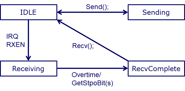
我这里用了一种状态处理机制,来保证485的半双工正常工作,简单来说就是收的时候不能发送发的时候不能接收,收发互斥。
但是这样做存在一个问题就是如果接受的数据没有及时处理,那么会造成一个死锁,接下来优化考虑用堆栈来接收数据,把接收到的数据压入栈,需要读的时候弹栈。