Forwarding and routing
2 important network-layer functions – forwarding and routing.
Forwarding: The router-local action of transferring a packet from an input link interface to the appropriate output link interface (within a single router).
Terms ‘forwarding’ and ‘switching’ are often used interchangeably.
Every router has a forwarding table. A router forwards a packet by examining the value of a field in the arriving packet’s header, and then using this header value to index into the router’s forwarding table. The value stored in the forwarding table entry for that header indicates the router’s outgoing link interface to which that packet is to be forwarded.
Routing: The network-wide process that determines the end-to-end paths that packets take from source to destination (involves all of a network’s routers).
Switches & routers
Packet switch: A general packet-switching device that transfer a packet from input link interface to output link interface, according to the value in a field in the header of the packet.
Link-layer switches: Packet switches that base their forwarding decision on values in the fields of the link layer frame. [layer 2 devices]
Routers: Packet switches that bases their forwarding decision on the value in the network layer field. [layer 3 devices]
Connection setup
Connection setup: The process of the routers along the chosen path from source to destination handshaking with each other in order to set up state before network-layer data packets can begin to flow.
Connection setup is an another important network-layer function required by some network-layer architectures. (e.g. ATM, frame relay, MPLS.)
Network service models
Network service model: defines the characteristics of end-to-end transport of packets between sending and receiving end systems.
Some possible services that the network layer could provide:
Guaranteed delivery; Guaranteed delivery with bounded delay; In-order packet delivery; Guaranteed minimal bandwidth; Guaranteed maximum jitter; Security services, etc.

The Internet’s network layer provides a single service – best-effort service.
Virtual circuit and datagram network
A network layer can provide connection and connectionless services between 2 hosts, which have some parallels with transport-layer connection-oriented and connectionless services. The crucial differences are:
1) In the network layer, host-to-to services are provided by the network layer for the transport layer;
In the transport layer, process-to-process services are provided by the transport layer for the application layer.
2) In many major computer network architectures, the network layer provides either a host-to-host connectionless service or a host-to-host connection service, but not both.
3) The transport-layer connection-oriented service is implemented at the edge of the network in the end systems;
The network-layer connection service is implemented in the routers in the network core as well as in the end systems.
Virtual-circuit network and datagram network are 2 fundamental classes of computer networks.
Virtual-circuit (VC) networks: Computer networks that provide only a connection service at the network layer. E.g. ATM, frame relay.
Datagram networks: Computer networks that provide only a connectionless service at the network layer. E.g. The Internet.
Virtual-circuit networks
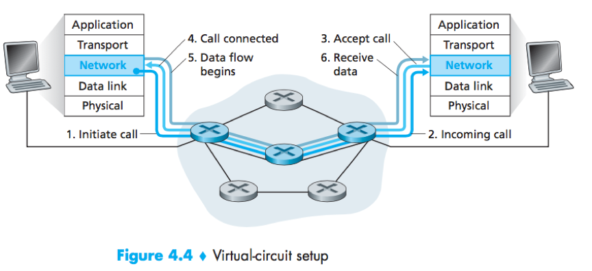
Virtual circuits (VCs): Network-layer connections used in VC networks. A VC consists of (1) a path (a series of links and routers) between the source and destination hosts; (2) VC numbers, one number for each link along the path; (3) entries in the forwarding table in each router along the path.
Each router has number translation in its forwarding table, so that it can replace the VC number of each traversing packet with a new VC number according to the forwarding table.
Signaling messages: The message that the end systems send into the network to initiate or terminate a VC, and the messages passed between the routers to set up the VC.
Signaling protocols: The protocols used to exchange signaling messages.
e.g. The forwarding table in a VC network router:

When a new VC is established across a router, an entry is added to the forwarding table;
When a VC terminates, the appropriate entries in each table along its path are removed.
Why a packet doesn’t just keep the same VC number on each of the links along its route?
1) To reduce the length of the VC field in the packet header;
2) To simplify VC setup (otherwise the routers have to exchange and process a substantial number of message to agree on a common VC number).
Each router must maintain connection state information for the ongoing connections.
3 phases in a VC:
1) VC setup:
The sending transport layer contacts the network layer, specifies the receiver’s address; ->
The network layer determines the path, and the VC number for each link along the path; ->
The network adds an entry in the forwarding table in each router along the path.
(The network layer may also reserve resources along the path.)
2) Data transfer:
Once the VC has been established, packets begin to flow along the VC.
3) VC teardown:
The sender or receiver informs the network layer of its desire to terminate the VC; ->
The network layer informs the end system on the other side of the call termination, and update the forwarding tables in each of the routers on the path to indicate that the VC no longer exists.
Distinction between the VC setup at the network layer and connection setup at the transport layer:
Transport-layer connection setup involves only the 2 end systems, only the 2 end systems are aware of the transport-layer connection.
Network-layer VC setup involves routers along the path, each router is aware of all the VCs passing through it.
Datagram networks
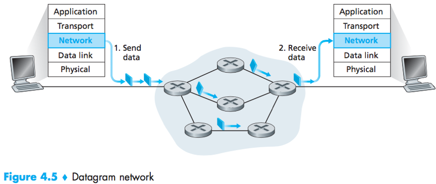
In a datagram network, each time an end system wants to send a packet, it stamps the packet with the address of the destination end system and then pops the packet into the network.
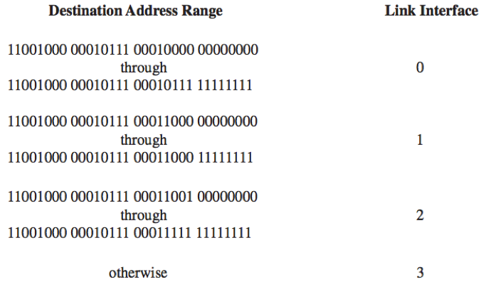
Each router has a forwarding table that maps destination address to link interfaces. When a packet arrives at a router, the router looks up the appropriate output link interface and forward the packet.
The router matches a prefix of the packet’s destination address with the entries in the table.
When there are multiple matches, the router uses the longest prefix matching rule – to choose the longest matching entry in the table.
e.g. The forwarding table in a datagram network router

(Meaning: )
Inside a router
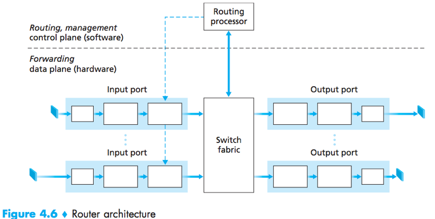
4 router components
Input ports:
Physical layer function – to terminate an incoming physical link at a router;
Link-layer functions – to interoperate with the link layer at the other side of the incoming link;
Lookup function – to use the forwarding table to determine the output port that an arriving packet will be forwarded via the switching fabric.
(Control packets: packets carrying routing protocol information, are forwarded from an input port to the routing processor.)
Switching fabric: through which that packets are switched from an input port to an output port.
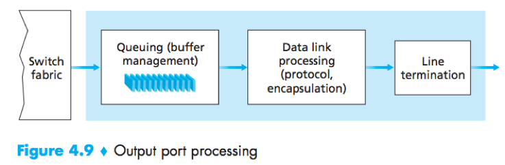
Output ports: stores packet received from the switching fabric and transmit them on the outgoing link (by performing link-layer and physical layer functions).
When a link is bidirectional, an output port will typically be paired with the input port for that link on the same line card.
Line card: a printed circuit board containing one or more input ports, which is connected to the switching fabric.
Routing processor:
Executes the routing protocols;
Maintains (updates) routing tables and attached link state information;
Computes the forwarding table for the router;
Performs the network management functions.
The router forwarding plane functions (i.e. the forwarding functions of a router) are always implemented in hardware, because they must operate at the nanosecond time scale – far too fast for software implementation.
The router control plane functions (i.e. the control functions of a router) are always implemented in software, because they operate at the millisecond or second timescale.
For today's Internet routers and routing algorithms, the network-wide routing control plane is decentralized -- with different pieces executing at different routers and interacting by sending control messages to each other.
Input Port Processing
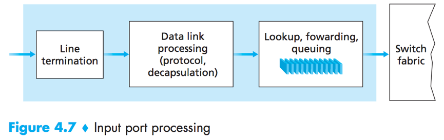
A shadow copy of the forwarding table (maintained by the routing processor) is stored at each input port, thus forwarding decisions can be made locally.
“Match plus action” is A general abstraction performed in many networked devices, the input port processing in a router is a special case. (“match” – looks up an IP address, “action” – sends the packet into the switching fabric.)
Switching
Switching can be accomplished in a number of ways:
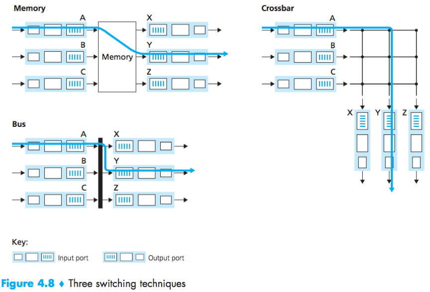
1) via memory
early routers – switching is done under direct control of the routing processor.
modern routers – the lookup of the destination address and the storing of the packet are performed by processing on the input line cards.
2) via a bus
An input port transfers a packet directly to the output port over a shared bus (without intervention by the routing processor).
The input port pre-pends a switch-internal label to the packet. All output ports receive the packet, but only the output port that matches the label will keep it.
3) via an interconnection network
crossbar switch: An interconnection network consisting of 2N buses that connect N input ports to N output ports.
Output Processing
Where does queueing occur
How much buffer is required to absorb the fluctuations in traffic load?
B – The amount of buffering; RTT – An average round-trip time; C – The link capacity; N – the number of TCP flows.
Early rule (for small N): B = RTT·C
Recent rule (for large N): B = RTT·C/√N
Packet queues may form at both the input ports and the output ports.
At output port –
1) A packet scheduler must choose one packet among those queued for transmission.
2) When there is not enough memory, a decision must be made to either drop the arriving packet (i.e. drop-tail) or remove one or more already-queued packets.
Active queue management (AQM) algorithms: Algorithms of packet-dropping and marking policies, used to drop (or mark the header of) a packet before the buffer is full.
Random Early Detection (RED) algorithm: One of the AQM algorithms. Under RED, a weighted average is maintained for the length of the output queue.
If the (average) queue length < the minimum threshold minth, the (newly arriving) packet will be admitted to the queue;
If the queue length > the maximum threshold maxth, the packet will be marked or dropped;
If the queue length is in [minth, maxth], the packet will be marked or dropped with a probability that is some function of the queue length, minth, and maxth.
At input port – If the switch fabric is not fast enough, packet queueing can also occur.
Head-of-the-line (HOL) blocking: The phenomenon that a queued packet in an input queue must wait for transfer through the fabric (even though its output port is free) because it is blocked by another packet at the head of the line.
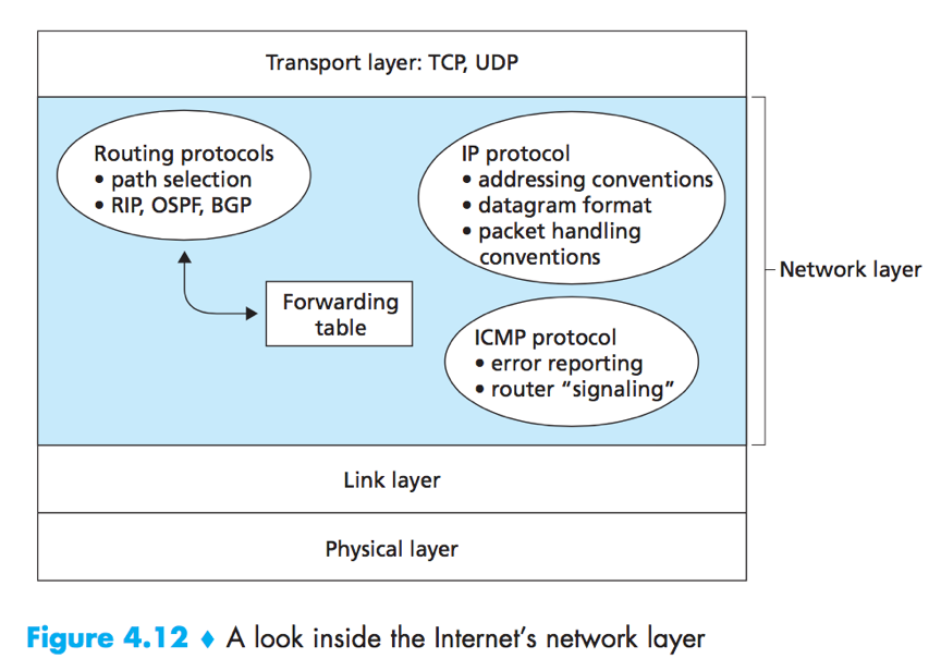
IP
The Internet’s network layer has 3 major components – 1) the IP protocol; 2) the Internet routing protocols e.g. RIP, OSPF, BGP; 3) facility to report and respond (ICMP)
IPv4
IPv4 Datagram format
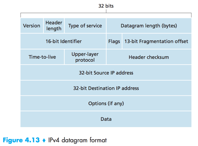
Version number (4 bits)
Header length (4 bits): used to determine where the data actually begins.
Type of service (TOS): used to allow different types of IP datagrams to be distinguished. E.g. datagrams that requires low delay/high throughput/reliability.
Datagram length (16 bits): the total length of the datagram (header+data).
Identifier, flags, fragmentation offset: have to do with IP fragmentation.
Time-to-live (TTL): used to ensure datagrams do not circulate forever. Each time the datagram is processed by a router, TTL-1. If TTL reaches 0, the datagram will be dropped.
Protocol: indicates the specific transport-layer protocol to which this datagram should be passed (used only when the datagram reaches its final destination).
Header checksum: aids in detecting bit errors, must be recomputed and stored again at each router.
Why does TCP/IP perform error checking in both the transport and network layers?
1) IP layer only checksums the IP header, TCP/UDP checksums the entire TCP/UDP segment; 2) TCP/UDP and IP do not necessarily have to belong to the same protocol stack.
Source and destination IP address
Options: allows an IP header to be extended. (were dropped in IPv6)
Data (payload): contains the transport-layer segment in most circumstances, can carry other data such as ICMP messages.
A typical IP datagram has a total of 20 bytes of header (assuming no options).
IP Datagram Fragmentation
MTU (the maximum transmission unit): The maximum amount of data that a link-layer frame can carry, depends on the link-layer protocol.
Problem: For a router that interconnects several links with different MTUs, how to squeeze oversized IP datagram into the link-layer frame (to send it to the link that has a smaller MTU)?
Solution: To fragment the data in the IP datagram into two or more smaller IP datagrams (i.e. fragment) and encapsulate these fragments in separate link-layer frames.
How to reassemble fragments before they reach the transport layer at the destination?
1) The sending host stamps the datagram with identification number, source address and destination address;
2) When a router needs to fragment a datagram, it stamps each resulting fragment with the identification number, source address and destination address of the original datagram:
The flag bit of the last fragment is set to 0, flag bits of all the other fragments are set to 1;
The offset field of each fragment specifies where the fragment fits within the original datagram.
3) At the destination, the payload of the datagram is passed to the transport layer only after the IP layer has fully reconstructed the original IP datagram.
Datagrams are reassembled in the end systems rather than network routers. (to keep the network core simple)
e.g. P337, Figure 4.14, TABLE 4.2.
Costs of fragmentation: 1) complicates routers and end systems; 2) can be used to create lethal DoS attacks.
IPv6 does away with fragmentation.
IPv4 Addressing
Interface: The boundary between the router/host and any one of its physical links. (a host typically has only a single link)
IP requires each host and router interface to have its own IP address. Each IP address is 32 bits (4 bytes) long.
Dotted-decimal notation: Each byte of the IP address is written in its decimal form, separated by a dot from other bytes. E.g. 11000001 00100000 11011000 00001001 -> 193.32.216.9.
Subnet: Detach each interface from its host or router, creating islands of isolated networks, with interfaces terminating the end points of the isolated networks. Each of these isolated networks is a subnet.
Subnet mask: /x notation that indicates the leftmost x bits of the 32-bit address define the subnet address. E.g. subnet address 223.1.1.0/24.
CIDR (Classless Interdomain Routing): The Internet’s address assignment strategy. As with subnet addressing, an IP address has the form a.b.c.d/x.
Prefix: The x leading bits of address a.b.c.d/x. An organization is typically assigned a range of addresses with a common prefix, only these x leading bits are considered by routers outside, the remaining 32-x bits are considered when forwarding packets at routers inside.
Classful addressing: Addressing scheme before CIDR, constrained network portion of IP addresses to be 8, 16 or 24 bits in length and subnet addresses were known as class A, B and C networks.
IP broadcast address: 255/255/255/255. When a host sends a datagram with this destination address, the message is delivered to all hosts on the same subnet. Routers optionally forward the message into neighboring subnets as well (though usually don’t).
1. Obtain a block of IP addresses (for use within an organization’s subnet)
ICANN allocates addresses to ISPs (through its regional Internet registries)-> The network administrator get a smaller block of addresses from its ISP.
2. Assign individual address to the host and router interfaces (in the organization)
Router addresseswill be manually configured by the system administrator typically;
Host addressescan also be configured manually, but more often is done using DHCP.
DHCP (Dynamic Host Configuration Protocol): A client-server protocol used to Allocate IP addresses to hosts automatically. A client is a typically newly arriving host wanting to obtain network configuration information.
A network administrator can configure DHCP so that a host 1) receives the same IP address each time it connects to the network; or 2) is assigned a temporary IP address that will be different each time it connects to the network.
DHCP is often referred to as a plug-and-play protocol.
DHCP also allows a host to learn additional information, e.g. its subnet mask; the address of its first-hop router (i.e. the default gateway); the address of its local DNS server.
DHCP is useful in residential Internet access network, wireless LANs and residential ISP access network.
4-step process of DHCP
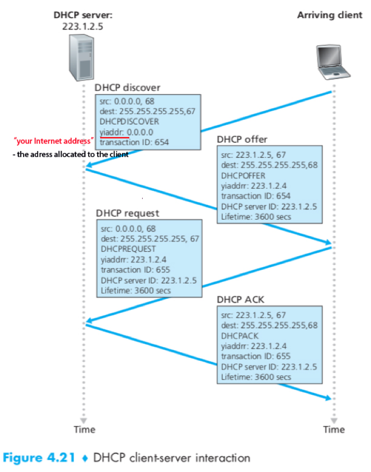
1) DHCP server discovery
The client passes an IP datagram that encapsulate DHCP discover message (a UDP packet to port 67), with broadcast destination IP address (255.255.255.255) and “this host” source IP address (0.0.0.0) to the link layer.
2) DHCP server offer(s)
A DHCP server responds with a DHCP offer message (contains the transaction ID of the received discover message, the proposed IP address for the client, the network mask and an IP address lease time) that is broadcast to all nodes on the subnet.
3) DHCP request
The client choose from among one or more server offers and respond to one with a DHCP request message, echoing back the configuration parameters.
4) DHCP ACK
The server responds with a DHCP ACK message, confirming the requested parameters.
NAT
Problem: In a realm with private addresses, addresses only have meaning to devices within that network, then how is addressing handled when packets are sent to or received from the global Internet?
Solution: NAT (network address translation). The NAT-enabled router behaves to the outside world as a single device with a single IP address.
How does the NAT-enable router know the internal host to which it should forward a given datagram?
Use a NAT translation table:
1) A host in the home network sends a request datagram to a server outside;
2) The NAT router receives the datagram, replaces the source IP address with its WAN-side IP address, replaces the source port number with a newly generated source port number (that is not currently in its NAT translation table), adds an entry to the NAT translation table, and send out the datagram;
3) The server outside responds with a datagram sent to the NAT router;
4) The NAT router indexes the NAT translation table to obtain the appropriate destination IP address and port number, rewrites the datagram and forwards it to the host.
Major Problem: NAT traversal for P2P application – a Peer B behind a NAT cannot accept TCP connection from a Peer A.
Solution: connection reversal– Peer A (if not behind a NAT) can first contact a intermediate Peer C, to which B has established an ongoing TCP connection, then ask B via C to initiate a TCP connection back.
UPnP
UPnP (Universal Plug and Play): A protocol that allows external host to initiate communication sessions to NATed hosts using either TCP or UDP. (provides effective NAT traversal solution.)
With UPnP, an application running in a host can request a NAT mapping between its (private IP address, private port number) and a (public IP address, public port number), thus the outside nodes can communicate with it.
ICMP
ICMP (Internet Control Message Protocol): used by hosts and routers to communicate network-layer information. Typical use: error reporting.
An ICMP message contains 1) type; 2) code field; 3) the first 8 bytes of the IP datagram that caused the message to be generated.
e.g. some well-known ICMP message types

ICMP architecturally lies just above IP (i.e. ICMP messages are carried as IP payload like TCP or UDP).
Traceroute program is implemented with ICMP messages.
IPv6
IPv6 Datagram Format
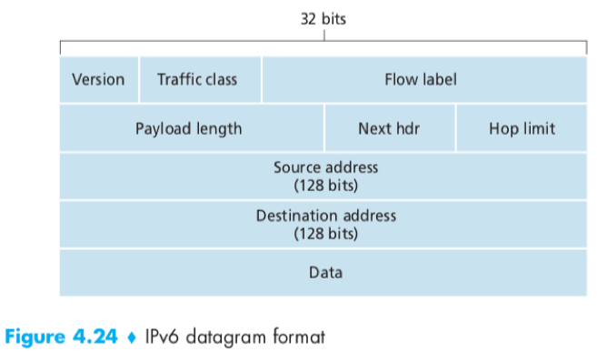
Version(4 bits)
Traffic class(8 bits): similar to the TOS field in IPv4, can be used to give priority to certain datagrams (e.g. within a flow, from certain applications).
Flow label(20 bits): identifies a flow of datagrams. (IPv6 allows labeling of packets belonging to particular flows for which the sender requests special handling.)
Payload length(16 bits): the number of bytes in the datagram following the fixed-length 40-byte header.
Next header: identifies the protocol (e.g. TCP, UDP) to which the data field will be delivered, similar to the protocol field in IPv4.
Hop limit: decremented by 1 by each router that forwards the datagram, if reaches 0, the datagram is discarded.
Source and destination addresses
Data: the payload portion.
IPv4 fields no longer present in IPv6: 1) Fragmentation/Reassembly; 2) header checksum; 3) Options.
If a router receives an IPv6 datagram that is too large, it simply drops the datagram and sends a “Packet Too Big” ICMPv6 error message back so that the sender can resend the data using a smaller datagram size.
Possible Options of How To Transition from IPv4 to IPv6
1. Dual-stack approach
IPv6/IPv4 node: A Node that have the ability to send and receive both IPv4 and IPv6 datagrams, can determine whether another node is IPv6-capable or IPv4 only and use corresponding datagrams when interoperating.
If either the sender or the receiver is only IPv4-capable, an IPv4 datagram must be used.
Cons: In conversion from IPv6 to IPv4, information in IPv6-specific fields will be lost.

2. Tunneling
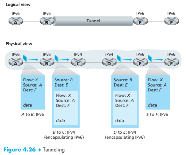
Tunnel: The intervening set of IPv4 routers between two IPv6 routers.
The IPv6 node on the sending side of the tunnel (B)puts the entire IPv6 datagram in the data field of an IPv4 datagram ->
The routers in the tunnel route this IPv4 datagram ->
The IPv6 node on the receiving side of the tunnel (E)extracts the IPv6 datagram and go on routing it.
Routing Algorithms
Ways to classify routing algorithms:
1. global or decentralized
Global routing algorithm: has complete information about connectivity and link costs before the calculation. E.g. LS.
Decentralized routing algorithm: Each node begins with only the knowledge of the costs of its own directly attached links, then calculates the path in an iterative distributed manner. E.g. DV.
2. static or dynamic
Static routing algorithm: routes change very slowly, often as a result of human intervention.
Dynamic routing algorithm: routes change as the network traffic loads or topology change.
3. load-sensitive or lead-insensitive
load-sensitive algorithm: link costs vary dynamically to reflect the current level of congestion in the underlying link.
load-insensitive algorithm: A link’s cost does not explicitly reflect its current level of congestion. (Today’s Internet routing algorithms)
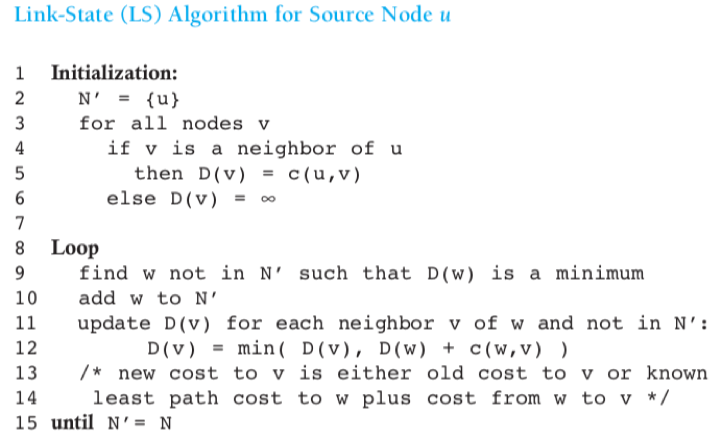
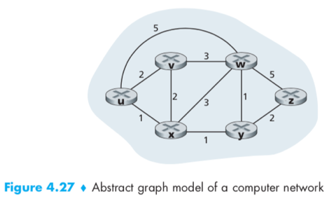
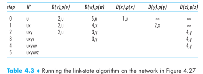
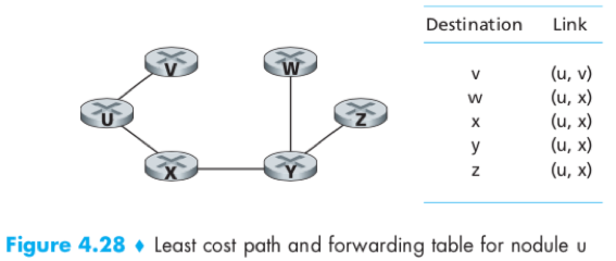
LS Algorithm
The link-state (LS) routing algorithm: In which the network topology and all link costs are known (accomplished by a link-state broadcast algorithm), each node can run the algorithm and compute the set of least-cost paths.
Dijkstra’s algorithm:
u – source node;
D(v) – cost of the least-cost path from u to destination v as of this iteration;
p(v) – previous node (v’s neighbour) along the current least-cost path from u to v;
N’ – a subset of nodes, v is in N’ if the least-cost path from u to v is definitively known.
e.g.
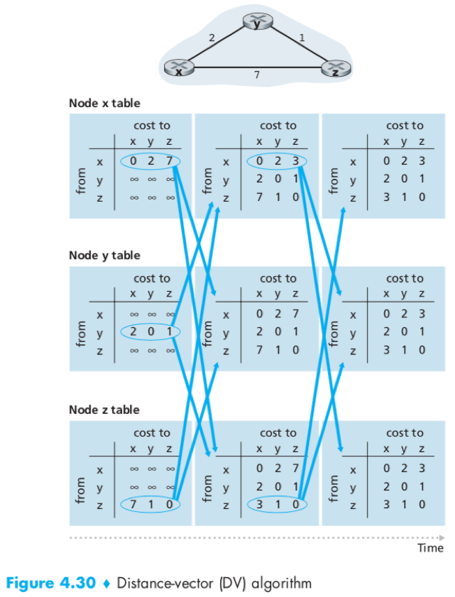
DV Algorithm
The Bellman-Ford equation: dx(y) = minv{c(x,v) + dv(y)}
dx(y) – the cost of the least-cost path from x to y.
v – one of x’s neighbors.
The distance-vector (DV) routing algorithm: is 1) distributed– each node receives information from its neighbors, calculates and distributes the result back; 2) iterative– the process continues until no more information is exchanged; 3) asynchronous– does not require all nodes to operate in lockstep.

Each node x maintains the following routing information:
1) The cost c(x,v) for each neighbour v;
2) distance vector Dx= [Dx(y): y in N] i.e. x’s estimate of its costs to all destinations y;
3) distance vector Dv= [Dv(y): y in N] of each neighbour v.
e.g.
routing loop caused by link-cost changes & poisoned reverse see P376-378.
DV algorithm may encounter routing loop, i.e. a packet destined for x arriving at y or z bounce back and forth between the 2 nodes until the forwarding tables changed.
Specific looping scenario can be avoided by using poisoned reverse, i.e. z lie to y that Dz(x)=∞and then y poisons the reverse path by informing Dy(x)=∞ after receiving the update. (but does not solve the general count-to-infinity problem.)
Compare LS & DV
Message complexity
Speed of convergence:
LS is an O(|N|2) algorithm requiring O(|N||E|) messages;
the time needed for DV to converge can depend on many factors, and DV may suffer from routing loops.
Robustness:
Route calculations are somewhat separated under LS, providing a degree of robustness;
An incorrect node calculation can be diffused through the entire network under DV.
LS and DV are essentially the only routing algorithms used in practice today in the Internet.
Other routing algorithms can include:
1) Algorithms based on viewing packet traffic as flows between sources and destinations;
2) Circuit-switched routing algorithms – of interest to packet-switched data networking.
Hierarchical Routing
Problem: In practice, the model of “all routers executing the same routing algorithm” is too simplistic.
Solution: to organize routers into ASs.
Autonomous system (AS): A collection of routers under the same administrative and technical control, and all that all run the same routing algorithms and have information about each other.
Intra-AS routing protocol: a.k.a. interior gateway protocol. The routing algorithm running within an AS (e.g. LS, DV), used to determine routing paths that are internal to the AS.
Gateway routers: One or more of the routers in an AS that is responsible for forwarding packets to destinations outside the AS.
How to route a packet to a destination outside the AS?
1) If the source AS has only 1 link that leads outside, just route the packet to the gateway router (through the path determined by the intra-AS routing algorithm), then the gateway forward it to the outside.
2) If the source AS has 2 or more links that leads outside, let the inter-AS routing protocol handle the tasks of “obtaining reachability information from neighboring ASs” and “propagating the reachability information to all routers internal to the AS”. Two communicating ASs must run the same inter-AS routing protocol.
- What if the destination is reachable via multiple gateways?
- A router need to determine to which gateway it should direct. e.g. one approach often employed –hot-potato routing (i.e. choose the gateway router that has smallest least cost.)
Routing in the Internet
RIP
RIP (Routing Information Protocol): A popular intra-AS Internet routing protocol, operates in a manner close to DV.
Hop: the number of subnets traversed along the shortest path from source router to destination subnet. RIP uses hop count as a cost metric.
RIP response message: a.k.a. RIP advertisement. Used to exchange routing updates between neighbors in RIP about every 30 seconds.
Routing table: A RIP table each router maintains, includes both the router’s distance vector and the router’s forwarding table. E.g.

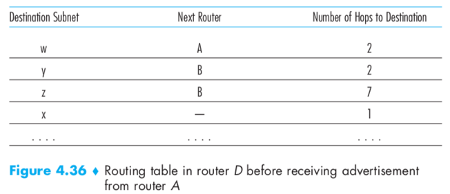
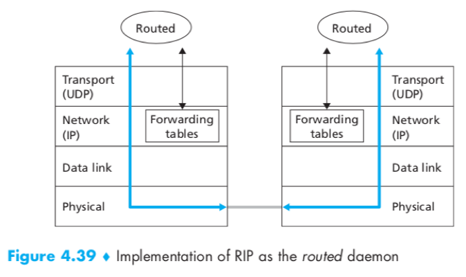
RIP is implemented as an application-layer process running over a transport-layer protocol (UDP) on top a network-layer protocol (IP).
OSPF
OSPF(Open Shortest Path First): Another popular intra-AS Internet routing protocol, is an LS protocol that uses link-state information and a Dijkstra’s algorithm. The “Open” indicates that the routing protocol specification is publicly available.
OSPF and its cousin IS-IS are typically deployed in upper-tier ISPs whereas RIP is deployed in lower-tier ISPs and enterprise networks.
OSPF doesn’t mandate how link weights are set (which is decided by the network administrator), only provides the mechanisms for determining least-cost path routing for the given set of link weights.
With OSPF, a router broadcasts routing to all other routers in the AS (whenever there is a change in a link’s state, also broadcast periodically even if there’s no change.), not just to its neighboring routers.
OSPF advertisements are contained in OSPF messages carried directly by IP, thus OSPF must itself implement functionality such as reliable message transfer and link-state broadcast.
Advances in OSPF:
1) Security – Exchanges between OSPF routers can be authenticated (simple authentication or MD5 authentication).
2) Multiple same-cost paths – allows multiple paths to be used when multiple paths to a destination have the same cost.
3) Integrated support for unicast and multicast routing – MOSPF (Multicast OSPF) extends OSPF, providing for multicast routing.
4) Support for hierarchy within a single routing domain – An OSPF autonomous system can be configured hierarchically: Each area runs its own OSPF algorithm; Within each area, one or more area border routers are responsible for routing packets outside the area; Exactly one OSPF area in the AS is configured as the backbone area.
BGP
BGP (Border Gateway Protocol): A standard inter-AS routing protocol, providing each AS a mean to 1) obtain subnet reachability information from neighbouring ASs 2) Propagate the reachability information to all routers internal to the AS 3) Determine routes to subnets.
In BGP, routers exchange routing information over semipermanent TCP connections using port 179.
BGP peers: The two routers at the end of each TCP connection.
BGP session: The TCP connection along with all the BGP messages sent over the connection.
External BGP (eBGP) session: A BGP session that spans two ASs.
Internal BGP (iBGP) session: A BGP session between routers in the same AS.
In BGP, destination are not hosts but instead are CIDRized prefixes, with each prefix representing a subnet or a collection of subnets.
e.g.
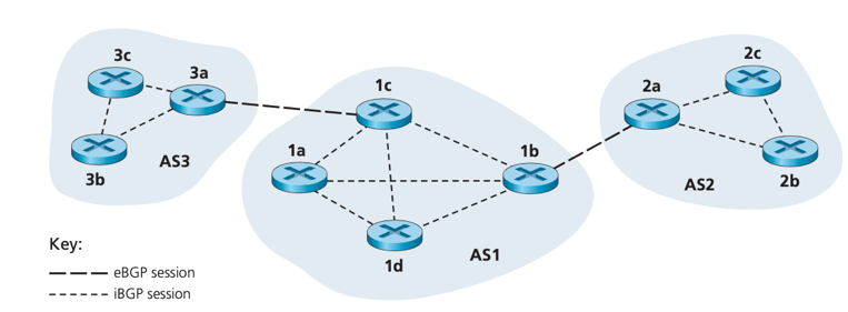
How BGP distribute prefix reachability information
· An AS can send another AS (AS1&AS3, AS1&AS2) the list of its reachable prefixes using eBGP session between their gateway routers (3a&1c, 1b&2a).
· In any AS, when a gateway router receives eBGP-learned prefixes, it uses its iBGP sessions to distribute prefixes to other routers inside the AS, then another gateway routers can re-advertise prefixes to another AS. (1c&1b, AS3->AS1->AS2)
· When a router learns about a new prefix, it creates an entry for that in its forwarding table.
BGP Attribute & BGP Route
Autonomous system number (ASN): In BGP, an autonomous system is identified by its globally unique ASN. (Technically, not every AS has an ASN. A stub AS that carried only traffic for a source or destination does not have an ASN.)
Route: A prefix along with its attributes. i.e. BGP peers advertise routes to each other.
BGP attributes: When a router advertises a prefix across a BGP session, it includes with the prefix with a number of BGP attributes. E.g. AS-PATH, NEXT-HOP.
AS-PATH: contains the ASNs of ASs through which the advertisement for the prefix has passed. When a prefix is passed into an AS, the AS add its ASN to the AS-PATH. -- Routers use AS-PATH to detect and prevent looping advertisement, and choose among multiple paths to the same prefix.
NEXT-HOP: the IP address of the router interface (A router has multiple IP addresses, one for each of its interfaces) that begins the AS-PATH (interface of the first router outside the router’s AS along the route). -- routes use NEXT-HOP to properly configure their forwarding tables.
e.g. when (gateway router) 3a advertises a route to (gateway router) 1c, NEXT-HOP is the IP address of 3a’s interface that leads to 1 c.

import policy: When a gateway router receives a route advertisement, it uses its import policy to decide whether to accept or filter the router and whether to set certain attributes (e.g. preference metrics).
BGP Route Selection
Problem: A router may learn about more than one route to any one prefix, in which case the router must select one.
Solution: If there are two or more routes to the same prefix, BGP sequentially invokes the following elimination rules until only one remains:
1) Select the route with the highest local preference values. (Local preference value: assigned to routers as one of their attributes.)
2) From remaining routes (with the same local preference value), select the route with the shortest AS-PATH.
3) From remaining routes (with same local preference value and AS-PATH length), select the route with the closest NEXT-HOP router. (closest: the router with the smallest cost of least-cost path determined by intra-AS algorithm. i.e. hot potato routing.)
4) If more than one route still remains, use BGP identifiers to select.
How a routing entry gets entered into a router’s forwarding table
(assume the prefix belongs to an AS outside the router’s AS)
(review: a routing entry consists of a prefix and an associated port. )
-> the router receives an advertisement via EBGP/iBGP session;
-> If the router receives more than one advertisement for this prefix, uses BGP route selection process to select a best route;
-> uses intra-AS routing protocol (typically OSPF) to determine the shortest path to the NEXT-HOP router; (review: each route has a NEXT-HOP attribute)
-> identifies the first link along that shortest path, associates the port number with the prefix;
-> enter the prefix-port pair into its forwarding table.
BGP’s routing policy
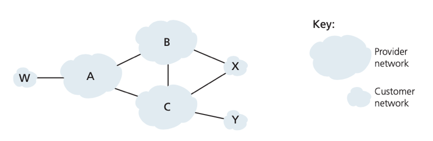
stub network: a network that traffic entering a it must be destined for it, and all traffic leaving that network must have originated in it. E.g. W, X, Y. in the picture
multi-homed stub network: stub network that connects to the rest of the network via multiple different providers while it must be the source/destination of all traffic leaving/entering it. E.g. X connects with B and C, but traffic B-X-C is prevented.
Problem: For a multi-homed stub network (custormer network), how will it be prevented from forwarding for others (provider network)? (e.g. X be prevented from forwarding traffic between B and C)
Solution: use a selective router advertisement policy to implement customer/provider routing relationship -- A stub network advertises no path to any other destination except itself. E.g. though X now path XCY, it never advertises this path to B, thus B never forward traffic destined to Y/C via X.
Why are different inter-AS and intra-AS routing protocol used?
There’s difference between the goal of routing within an AS and among ASs.
1) Policy – Policy issues are more important among ASs than within an AS (because within a single AS, everything is under the same administrative).
2) Scale – The ability to handle routing among large number of networks is more of concern among ASs than within an AS (because when a single AS is too large, it can be divided into multiple new ASs and perform inter-AS routing instead).
3) Performance – Performance is less of concern among ASs (because inter-AS routing should so focus on policy first) than within an AS.
Broadcast and Multicast Routing
Unicast routing: a source node sends a packet to a single destination node.
Broadcast routing: a source node sends a packet to all other nodes in the network.
Multicast routing: a source node sends a packet to a subnet of the other network nodes.
Broadcast Routing Algorithm
N-way-unicast: a straightforward approach to accomplish broadcast communication, let the sending node send a separate copy of the packet to each destination.

N-way-unicast has several drawbacks:
1) inefficiency. separate copies of the same packet will traverse the same single link (a); could be more efficient for the network node themselves (instead of just the source node) to create copies (b).
2) In situation where broadcast is used to create/update unicast routes (e.g. link-state routing protocol uses broadcast to disseminate LS information used to compute routes), it would be unwise to rely on unicast routing
Flooding
Flooding: an approach to achieve broadcast --Let the source node send a copy of the packet to all its neighbors, , each node duplicates the received broadcast packet and forward to all its neighbors (except the neighbour from which it received the packet) too.
Problem: uncontrolled flooding causes Broadcast storm because one or more copies of broadcast packets will cycle indefinitely if the graph has cycles.
Solution: controlled flooding judiciously chooses when to flood a packet and when not to. Approaches to controlled flooding:
1) sequence-number-controlled flooding: e.g. the Gnutella protocol
source node puts its address (or other unique identifier) and a broadcast sequence number into the broadcast packet;
Each node maintains a list of the source address and sequence number of each broadcast packet it has already received/duplicated/forwarded;
When a node receives a broadcast packet, check whether the packet is in the list:
-> If so, drop the packet;
-> If not, duplicate and forward the packet to all neighbours (except which it was sent from);
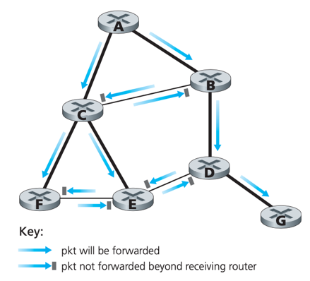
2) reverse path forwarding (RPF): a.k.a. reverse path broadcast (RPB)
When a router receives a broadcast packet with a given source address, it transmits the packet on all of its outgoing links (except the neighbour from which it received the packet) only if the packet arrived on the link that is on its own shortest unicast path back to the source.
Note: RPF does not require a router know the complete shortest path, only need to know the next neighbour on the shortest unicast path to the source to determine whether to flood a packet.
e.g. (think lines represents the least-cost paths from source A to each node)
Spanning-Tree Broadcast
Problem: sequence-number-controlled flooding/RPF do not completely avoid transmission of redundant broadcast packets. – need an approach that every node receives only one copy
Solution: Spanning-tree broadcast
-> Source node sends the packet out on all incident links that belong to the spanning tree; Each node forward the received packet to all its neighbours in the spanning tree (except the neighbour from which it received the packet).
Spanning tree: given a graph G=(N,E), a spanning tree is a graph G’=(N,E’) such that E’ is a subset of E, G’ is connected and G’ contains no cycles, and G’ contains all the original nodes in G.
Minimum spanning tree: the spanning tree with the minimum cost of all of the graph’s spanning trees.
Spanning tree can be used by any node to begin a broadcast. E.g.

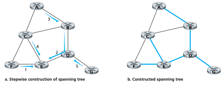
center-based approach: a spanning-tree creation algorithm. ####needsEDITS
-> define a center node (a.k.a. rendezvous point, core);
-> nodes unicast tree-join messages addressed to the center node.
-> A tree-join message is forwarded using unicast routing until it either a) arrives at a node that already belongs to the spanning tree or b) arrives at the center.
--> finally, paths that the tree-join message has followed define braches of the spanning tree.
E.g. the construction of a spanning tree with center E.
Multicast
Problem: how to identify receivers/how to address packet in multicast? (carrying IP addresses of all recipients for each packet would swamp the payload)
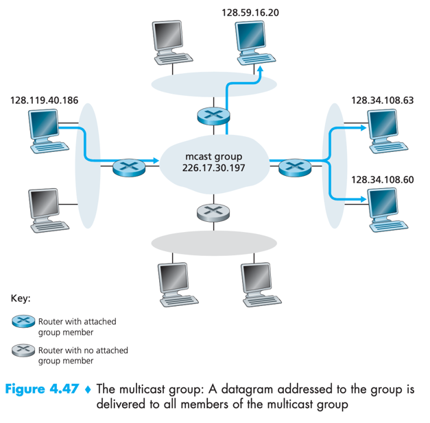
Solution: in the Internet architecture, a multicast packet is addressed using address indirection.
Address indirection: a single identifier is used for the group of multicast receivers, and a copy of the packet that is addressed to the group using this identifier is delivered to all receivers associated with that group.
In the Internet, this single identifier is a class D multicast IP address. The group of receivers associated with a class D address is a multicast group.
e.g. hosts associated with multicast group address 226.17.30.197 will received datagrams addressed to that address.
IGMP
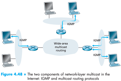
Network-layer multicast in the Internet consists of two components: 1) IGMP; 2) (network-layer) multicast routing protocols.
Network-layer multicast routing protocols: coordinate the multicast routers throughout the Internet.
Internet Group Management Protocol (IGMP): provides the means for a host to inform its attached router that an application running on the host wants to join a specific multicast group.
IGMP has 3 message types: 1) membership_query; 2) membership_report; 3) leave_group.
membership_query message: is sent by a router to all hosts on an attached interface to determine the set of all multicast groups that have been joined by the hosts on that interface.
membership_report message: is sent by a host either a) to respond to a membership_query message or b) when an application first joins a multicast group without waiting for a membership_query message.
leave_group message: is optional, because router can infer that a host is no longer in the multicast group if it no longer responds to a membership_query message. – an example of soft state
soft state: In a soft-state protocol, the state (e.g. for IGMP, the fact that there are hosts joined to a given multicast group) is removed via a timeout event (e.g. for IGMP, a periodic membership_query message) if it is not explicitly refreshed (e.g. for IGMP, refreshed by a membership_report message from an attached host).
Multicast Routing Algorithm

goal: to find a tree of links that connects all routers that have attached hosts belonging to the multicast group.
2 approaches to determine the multicast routing tree:
a) using a group-shared tree – a single tree for all senders in the group
Use a center-based approach to build a spanning tree (which includes all edge routers with attached hosts belonging to the multicast group).
b) using a source-based tree – one tree for each source
use RPF to construct a multicast forwarding tree for each source.
Problem: under broadcast RPF, multicast packets may be forwarded to some routers that has no attached hosts that are joined to the group. E.g. router D, G.
Solution: pruning – a router that receives multicast packets and has no attached host joined to that group will send a prune message to its upstream router. If a router receives prune message from all its downstream routers, it can forward a prune message upstream.
Multicast Routing in the Internet
Distance-Vector Multicast Routing Protocol (DVMRP): the first internet multicast routing protocol, implements source-based trees with RPF and pruning.
Protocol-Independent Multicast (PIM) routing protocol: perhaps the most widely used Internet multicast routing protocol, explicitly recognizes 2 scenarios:
a) dense mode: in which multicast group members are densely located. Uses flood-and prune RPF.
b) sparse mode: in which multicast group members are widely dispersed. Uses rendezvous points to set up multicast distribution tree.
Source-specific multicast (SSM): in which only a single sender is allowed to send traffic into the multicast tree, construction & maintenance are simplified a lot.
Problem: how can IP multicast routers be configured between different domains (like BGP for unicast)?
Solution: multiprotocol extensions to BGP allows it to carry routing information for other protocols, including multicast information.