Node: any device that runs a link-layer protocol. E.g. hosts, routers, switches, WiFi access points.
Link: communication channel that connects adjacent nodes along the communication path.
Over a given link, a transmitting node encapsulates the datagram in a link-layer frame and transmits the frame from one node to another.
Services Provided by the Link Layer
Possible services offered by a link-layer protocol include:
a) Framing
Almost all link-layer protocols encapsulate each network-layer datagram within a link-layer frame before transmission over the link;
b) Link access
A medium access control (MAC) protocol specifies the rules by which a frame is transmitted onto the link – when multiple nodes share a single broadcast link, MAC coordinates the frame transmission;
c) Reliable delivery
similar to transport-layer reliable delivery service, can be achieved with acknowledgments & retransmissions.
often used for links that are prone to high error rates e.g. wireless link.
Can be considered unnecessary overhead for low bit-error links e.g. wired link.
d) Error detection and correction
done by transmitting node including error-detection bits in the frame & receiving node performing error check.
Is more sophisticated & implemented in hardware compared to transport-layer error detection.
Where Is the Link Layer Implemented
A router’s link layer is implemented in the router’s line card;
A host’s link layered is implemented in Network adapter: a.k.a. network interface card (NIC).
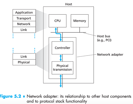
link-layer controller: inside a network adapter, usually a single, special-purpose chip that implements many link-layer services in hardware.
While most of the link layer is implemented in hardware, part of it is implemented in software (running on the host’s CPU). E.g. assembling link-layer addressing information, activating the controller hardware.
Error-Detection and –Correction Techniques
Parity Checks
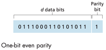
Parity checks with single parity bit: the total number of 1s in the d+1 bits (original information + parity bit) is even for even parity schemes, or odd for odd parity schemes.
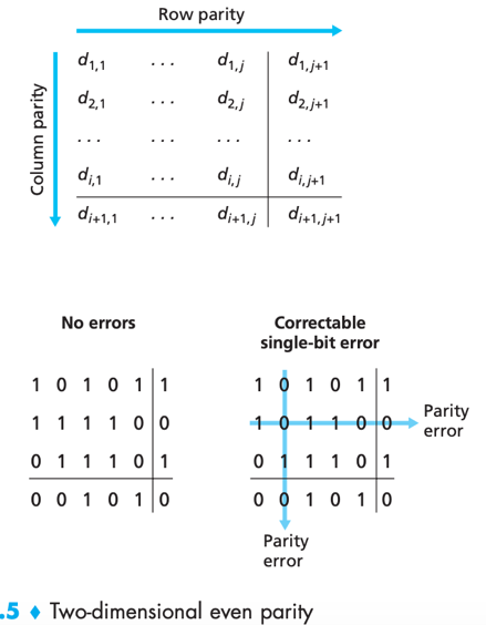
In two-dimensional parity scheme, when a bit is flipped, receiver can use the column and row indices of the column and row with parity errors to identify the corrupted bit.
Forward error correction (EFC): The ability of the receiver to both detect and correct errors.
EFC techniques are important for real-time network apps or links with long propagation delays because by allowing for immediate correction at the receiver they avoid waiting for NAK & retransmitted packet.
Checksumming
Internet checksum: bytes of data are treated as 16-bit integers and summed, the 1s complement of this sum forms the checksum. --> receiver will take the 1s complement of the sum of received data (including checksum), see if the result is all 1 bits.
Compared to CRC, checksumming requires little packet overhead but weaker protection against errors.
Why is checksumming usually used at transport layer & CRC usually used at link layer?
1) transport-layer error detection is implemented in software, better to have a simple and fast error-detection scheme like checksumming;
2) link layer error detection is implemented in hardware, which can rapidly perform the more complex CRC operations.
CRC
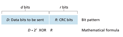
Cyclic redundancy check (CRC) codes: a.k.a. polynomial codes.
-> Sender and receiver first agree on generator G (r+1 bits);
-> sender computes an R via ![]()
-> sender appends this additional R (r bits) to data D (d bits);
-> receiver divides (using modulo-2 arithmetic) the received d+r bits by G -- If remainder is nonzero, error has occurred. i.e. ![]()
Multiple Access Links and Protocols
There are 2 types of network links: point-to-point link and broadcast link.
point-to-point link: consists of a single sender at one end and a single receiver at the other end of the link. E.g. point-to-point protocol (PPP), high-level data link control (HDLC).
broadcast link: can have multiple sending and receiving nodes, all connected to the same single shared broadcast channel. E.g. Ethernet, wireless LANs.
Multiple access problem: how to coordinate the access of multiple sending and receiving nodes to a shared broadcast channel.
– when multiple nodes can transmit frames at the same time, transmitted frames will collide at receivers and make no sense thus waste broadcast channel.
Multiple access protocols: by which nodes regulate their transmission into the shared broadcast channel, avoiding collision.
Desirable characteristics of a multiple access protocol:
1) When only 1 node has data to send, the node has a throughput of R bps (R: the rate of the broadcast channel);
2) When M nodes have data to send, each has a throughput of R/M bps (average, not necessarily instantaneous);
3) decentralized i.e. there is no master node that represents a single point of failure for the network;
4) simple, inexpensive to implement.
Any multiple access protocol belongs to one of the 3 categories: channel partitioning protocols, random access protocols and taking-turns protocols.
Channel Partitioning Protocols
(suppose the channel supports N nodes and has a transmission rate of R bps)
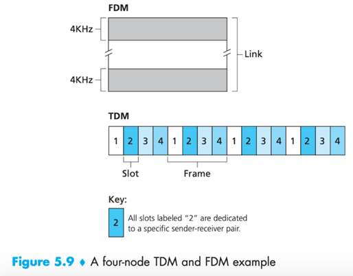
1. Time-division multiplexing (TDM): divides time into time frames, further divides each time frame into N time slots, assign each time slot to one of the N nodes. Whenever a node has packet to send, it transmits the packet’s bit during its assigned time slot.
// “time frames” (as time unit) here should not be confused with “link-layer frame” (as data unit, referred as packet here).
Pros:
Avoids collisions & Fair -- each node gets a dedicated transmission rate of R/N bps.
Cons:
1) A node is limited to an average rate of R/N bps even when it is the only node with packets to send;
2) A node must always wait for its turn in the transmission sequence, even when it is the only node with packets to send.
2. Frequency-division multiplexing (FDM): divides the R bps channel into different frequencies, each with a bandwidth of R/N, and assign each frequency (i.e. smaller channel) to one of the N nodes.
Pros:
Avoid collision & Fair. (same as TDM)
Cons:
A node is limited a bandwidth of R/N even when it is the only node with packets to send.
e.g.
3. Code division multiple access (CDMA): Assigns a different code to each node, each node then uses its unique code to encode the data bits it sends.
Pros: if codes are chosen carefully, different nodes can transmit simultaneously yet have receivers correctly receive encoded data bits in spite of interfering transmissions by other nodes.
Random Access Protocols
In a random access protocol, a transmitting node always transmits at full rate of the channel (R bps).
When there is a collision, each node involved in the collision waits a random delay (chosen independently) before retransmission, repeatedly retransmits its frame until the frame gets through without a collision.
Random access protocols examples: ALOHA protocol, CSMA protocol, Ethernet.
ALOHA
Slotted ALOHA
-> divide time into slots;
-> requires slots to be synchronized in nodes.
-> (independently,) If a node detects a collision, it retransmits its frame in each subsequent slot with probability p until the frame is transmitted without a collision.
Pros:
- allows a node to transmit at full rate R when that node is the only active node; (*active node: node that has frames to send.)
- simple, highly decentralized;
Cons:
- efficiency is not high.
efficiency
* successful slot: A slot in which exactly one node transmits.
Slots that is not successful will be wasted.
- a: when there are multiple active nodes, some slots will have collision;
- b: when all active nodes refrain from transmitting due to retransmission probability.
Efficiency: the long-run fraction of successful slots when there are a large number of active nodes, each always having a large number of frames to send.
When there are N active nodes, the efficiency of slotted ALOHA is Np(1-p)N-1, with maximum efficiency 1/e=0.37.
ALOHA: Pure ALOHA does not require slotting or synchronization.
Node transmits its frame immediately when the network-layer datagram is passed down. When there is a collision, node will immediately retransmit the frame with probability p.
-- Fully decentralized.
When there are N active nodes, the efficiency of pure ALOHA is Np(1-p)2(N-1), with maximum efficiency 1/(2e), i.e. half of slotted ALOHA.
CSMA
The family of carrier sense multiple access (CSMA) and CSMA with collision detection (CSMA/CD) protocols embody 2 rules: carrier sensing and collision detection.
Carrier sensing: a node listens to the channel before transmitting. If a frame from another node is currently being transmitted into the channel, a node waits until it detects no transmissions for a short time and then begins transmission.
Collision detection: A node listens to the channel while it is transmitting. If it detects that another node is transmitting an interfering frame, it stops transmitting and waits a random amount of time (i.e. backoff time) before repeating the sense-and-transmit-when-idle cycle.
The end-to-end channel propagation delay of the broadcast channel plays a crucial role in determining CSMA’s performance -- the longer the delay, the larger the chance a carrier-sensing node not yet able to sense a transmission has already begun at another node.

Question: For CSMA/CD, what is a good interval of time from which to choose the random backoff time?
Answer: a short interval for a small number of colliding nodes, a long interval for a large number of colliding nodes.
Binary exponential backoff algorithm: solves the problem of picking good random backoff time interval.
-> When transmitting a frame that has already experienced n collisions, a node chooses value K at random from {0, 1, 2, …, 2n-1}.
-> K∝backoff time. the maximum value that n can take is capped at 10.
Thus the size of the sets from which K is chosen grows exponentially with the number of collision.
e.g. For Ethernet, a node waits K·512 bit times (K times the amount of time needed to send 512 bits into the Ethernet).
CMSA/CD Efficiency

dprop: the maximum time it takes signal energy to propagate between any two adapters;
dtrans: the time to transmit a maximum-size frame;
As dprop->0, colliding nodes can abort immediately without wasting the channel, thus Efficiency->1;
As dtrans->∞, a frame can hold on to the channel for a very long time, the channel will be doing productive work most of the time thus Efficiency->1.
Taking-Turns Protocols
Taking-turns protocols: multiple access protocols that achieve desired property “when M nodes are active, each active node has a throughput of nearly R/M bps”. e.g. polling protocol, token-passing protocol.
Polling protocol: e.g. 802.15 protocol; Bluetooth protocol.
-> designate one of the node as a master node.
-> The master node polls each node in a round-robin fashion:
--> master node sends a message to a node, saying that node can transmit up to some maximum number of frames;
--> after that node transmits some frames, master node go on to tell next node;
…;
pros: eliminate collision and empty slots.
cons: 1) introduces polling delay (time to notify a node); 2) if the master node fails, the entire channel fails.
Token-passing protocol: e.g. FDDI; IEEE 802.5 token ring protocol.
A token (*a small, special-purpose frame) is exchanged among nodes in some fixed order; e.g. (ode 1 always send the token to node 2, node 2 always send the token to node 3, …, node N always send to node 1).
-> When a node receives a token:
--> if it has frames to transmit, it sends up to a maximum number of frames, then forwards the token to the next node;
--> otherwise if it does not have frame to transmit, it immediately forwards to token to the next node;
Pros: decentralized, efficient;
Cons: one node’s failure can crash the entire channel.
DOCSIS
cable access network serves as an example of multiple access protocols in action (FDM, TDM, random access, centrally allocated time slots.)
Data-Over-Cable Service Interface Specifications (DOCSIS): specifies the cable data network architecture and its protocols.
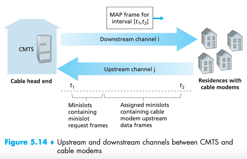
*CMTS: cable modem termination system
- uses FDM to divide downstream (CMTS to modem) and upstream (modem to CMTS) network segments into multiple frequency channels;
- each upstream channel is divided into intervals of time (TDM-like), each containing a sequence of mini-slots (for transmitting a. minislot request frames and b. data frames);
- cable modems (that have data to send) send mini-slot-request frames to CMTS during a special set of mini-slots, in random access manner;
- CMTS sends a control message (MAP message) on downstream channel to specify which cable modem (that has data to send) can transmit during which mini-slot;
- cable modems infer its mini-slot-request frames experienced a collision if it does not receive a response in the next downstream control message, it uses binary exponential backoff to defer retransmission of its mini-slot request frame;
- When there is little traffic on upstream channel, cable modem may transmit data frames during slots nominally assigned for mini-slot-request frames (thus avoid waiting for mini-slot assignment).
Switched Local Area Networks
Switches operating at link layer don’t recognize network-layer IP addresses, (and don’t use routing algorithms like RIP or OSPF,) they use link-layer addresses instead.
Link-Layer Addressing
Switches operating at link layer don’t recognize network-layer IP addresses, (don’t use routing algorithms like RIP or OSPF,) instead they use link-layer addresses to forward layer frames.
MAC address
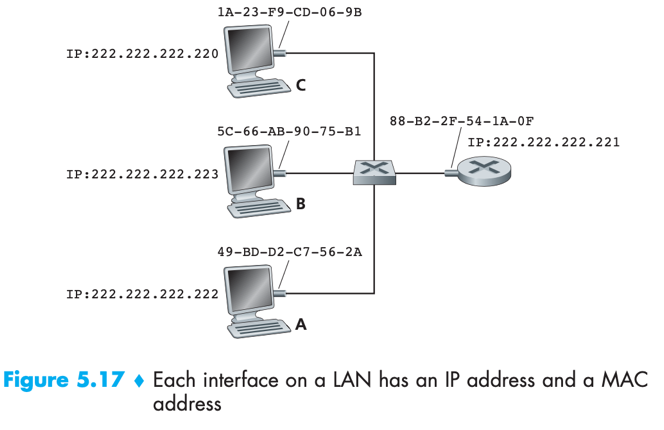
A host/router with multiple network interfaces (adapters) have multiple link-layer addresses associated with it. (same does multiple IP addresses);
Link-layer switches do not have link-layer addresses associated with their interfaces. – because a switch’s job is just to carry datagrams between hosts and routers, doesn’t have to explicitly address the frame to intervening switch.
MAC address: a.k.a. LAN address, physical address. link-layer address. For most LAN, MAC address is 6 bytes long (248 possibilities), with each byte expressed as a pair of hexadecimal numbers.
-> When an adapter wants to send a frame to some destination adapter, sending adapter inserts destination adapter’s MAC address into the frame and then sends the frame into LAN.
-> a switch occasionally broadcast an incoming frame onto all of its interfaces;
-> When an adapter receives a frame, it checks whether the destination MAC address in the frame matches its own MAC address.
--> a. If there is a match, the adapter extracts the enclosed datagram and passes it up the protocol stack;
--> b. If there isn’t a match, the adapter discards the frame.
-> If sending adapter does want all other adapters to receive its frame, it inserts a special MAC broadcast address into the frame’s destination address field. e.g. for LAN, broadcast address is a string of 48 consecutive 1s (FF-FF-FF-FF-FF-FF).
No two adapters have the same address.
=> IEEE manages MAC address space. When a company wants to manufacture adapters, IEEE allocates a chunk of address space (consisting of 224 addresses) with first 24 bits fixed. The company itself creates unique combination of the rest 24 bits.
MAC address has a flat structure, IP address has a hierarchical structure.
=> An adapter’s MAC address doesn’t change no matter where it goes. A host/router ’s IP address changes when it moves to another network.
Why hosts and routers interfaces have MAC address in addition to network-layer address?
=> 1) LANs are designed for arbitrary network-layer protocols, not just for IP/Internet. If adapter were assigned IP address only, they would not easily be able to support other network-layer protocols (e.g. IPX, DECnet).
2) if adapters were to use network-layer address instead of MAC address, network-layer address would have to be stored in adapter RAM and reconfigured every time the adapter is moved. (if not using any address in adapters and have adapters pass received data up the protocol stack for network layer to check network-layer address, the host would be interrupted by every frame sent on the LAN including frames not destined for it.)
ARP
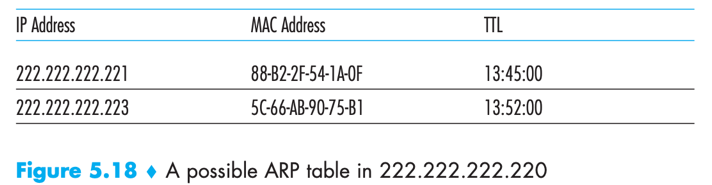
Address Resolution Protocol (ARP): for hosts and router interfaces on the same subnet, resolves an IP address to a MAC address.
ARP table: Each host and router has an ARP table in its memory, which contains mappings IP addresses to MAC addresses and a time-to-live (TTL) value (indicating when each mapping will be deleted from the table).
ARP table gets built automatically, it doesn’t have to be configured by a system administrator.
If a host becomes disconnected from the subnet, its entry is eventually deleted from other ARP tables in the subnet.
e.g.
What if the ARP table doesn’t currently have an entry for the destination?
-> the sender passes an ARP query packet to its adapter;
-> source adapter encapsulates the ARP query packet in a link-layer frame with broadcast address as destination address; //ARP query packet is sent within a broadcast frame
-> source adapter transmits the frame into the subnet, the frame is received by all other adapters on the subnet;
-> each adapter passes the ARP packet within the frame up to its ARP module;
-> Each of these ARP modules checks to see if its IP address matches the destination IP address in the ARP query packet;
-> The one with a match sends back to the querying host a response ARP packet with the desired mapping; //ARP response packet is sent within a standard frame
-> the querying host updates its ARP table, and sends a frame to the destination MAC that responded to the earlier query.
Q: Is ARP a link-layer protocol or a network-layer protocol?
A: an ARP packet has fields containing both link-layer addresses and network-layer addresses, thus ARP is probably best considered a protocol that straddles the boundary between link and network layers.
How to send a datagram off the subnet
e.g. 111.111.111.111 (at subnet 1) sends to 222.222.222.222 (at subnet 2)

-> sending adapter sends the frame into subnet 1, with [the first-hop router on the path to final destination]’s router interface (111.111.111.110) ’s MAC address (E6-E9-00-17-BB-4B) (obtained via ARP) as destination;
-> the router adapter receives the frame, passes the datagram up to its network layer;
-> via consulting forwarding table, the router determines the correct interface (222.222.222.220) to forward then forward the datagram;
-> the interface passes the datagram to its adapter, which encapsulates the datagram in a new frame with new destination MAC address (49-BD-D2-C7-56-2A)(obtained via ARP), then sends the frame into Subnet 2;
ARP Packet Structure
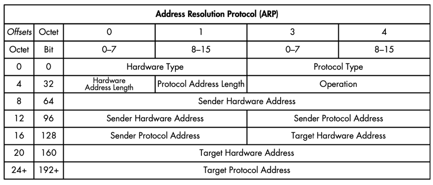
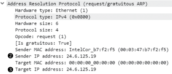
Gratuitous ARP
Gratuitous ARP packet: broadcast to notify receiving devices to update its cache with new IP-to-MAC address mapping. In ARP header, it looks like ARP request except the sender and target IP address are the same.
e.g. a gratuitous ARP packet
Ethernet
Ethernet: by far the most prevalent wired LAN technology.
Ethernet Frame Structure

Data field (46 to 1500 bytes): carries IP datagram (can also carry other network-layer packets).
IP datagram >1500 bytes or <46 bytes has to be fragmented or stuff the data field. (network layer will uses IP datagram header ’s length field to remove the stuffed part.)
Destination address (6 bytes): contains MAC address of the destination adapter.
When an adapter receives an Ethernet frame with matched destination address/broadcast address, it passes the frame’s data field to network layer, or else discards the frame.
Source address (6 bytes): contains MAC address of the source adapter.
Type field (2 bytes): permits Ethernet to multiplex network-layer protocol.
IP, other network-layer protocols (e.g. Novell IPX, AppleTalk) and ARP have their own type number. Via type field an adapter can know onto which network-layer protocol it should demultiplex the data field.
Cyclic redundancy check (CRC) (4 bytes): allows the receiving adapter to detect bit errors in the frame.
Preamble (8 bytes): for synchronizing the receiving adapter’s clock to sending adapter’s (synchronization is needed because in real transmission there’s always some drift from the sender’s target rate). First 7 bytes all have value 10101010 (for receiver to lock onto sender’s clock) the last byte has 10101011 (last 2 bits i.e. first consecutive 1s alert the follow-up content).
Ethernet Technologies
Ethernet technologies provide an unreliable connectionless service. When a received frame passes/fails CRC check, receiver won’t send back acknowledgment. But gaps in Ethernet won’t affect applications who using TCP, because TCP will ask to retransmit if there’s loss.
In old days, original hub-based Ethernet need to include CSMA/CD protocol for dealing with frame collisions because hub-based star topology is a broadcast LAN. Today’s switch-based Ethernet has no need for a MAC protocol because a modern full-duplex switch can coordinate its transmissions and there will be no collisions.
*hub: a physical-layer device that acts on individual bits. Whenever a hub receives a 0/1 bit from one of its interfaces, it sends (broadcasts) a copy onto all its other interfaces. Hub was replaced by switch in early 2000s.
Link-Layer Switches
Switch: works to receive incoming link-layer frames and forward them onto outgoing links.
Forwarding & Filtering
Filtering: switch function that determines whether a frame should be forwarded to some interface or should just be dropped.
Forwarding: switch function that determines the interfaces to which a frame should be directed, then moves the frame to those interfaces.
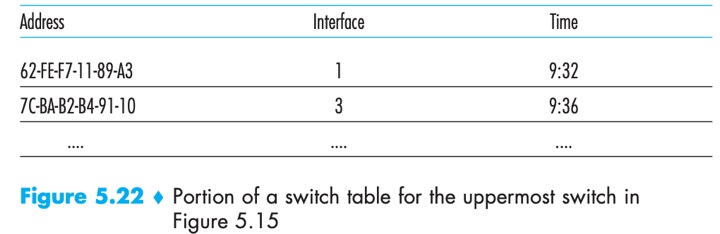
Switch filtering and forwarding are done with a switch table.
Switch table: contains entries for some hosts/routers on a LAN. Each entry contains: 1) MAC address; 2) switch interface that leads toward that MAC address; and 3) time at which the entry was placed. e.g.
how switch filtering and forwarding work?
-> a frame arrives at the switch on some interface x;
-> the switch indexes its table with the frame’s destination MAC address;
a) If there is no matching entry in the table, the switch broadcast the frame to all interfaces except x;
b) If there is a matching entry with interface x, the switch discards the frame because there is no need to forward;
c) If there is matching entry with interface y≠x, the switch put the frame in an output buffer that precedes interface y.
Self-Learning
Switches are self-learning. A switch can build its switch table automatically, dynamically and autonomously (plug-and-play) without intervention from network administrator.
How to accomplish self-learning?
-> The switch table is initially empty;
-> For each incoming frame received, the switch stores in its table:
1) MAC address in the frame’s source address field
2) interface from which the frame arrived
3) current time;
-> The switch deletes an address in the table if no frames are received with that address as source address after some period of time (aging time).
switches are also full-duplex, any switch interface can send and receive at the same time.
advantages of using switches over broadcast links such as buses/hub-based star topologies
- Elimination of collisions
switches can buffer frames and never transmit more than one frame on a segment at any one time thus there is no wasted bandwidth due to collisions.
- allow Heterogeneous links
A switch isolates one link from another thus different links in the LAN can operate at different speeds and run over different media.
- ease Management
e.g. If an adapter malfunctions and continually sends Ethernet frames (a.k.a. a jabbering adapter), a switch can detect and internally disconnect the malfunctioning adapter without intervention from network administrator. – doubt: seems contradict to statements in “Switches v.s. Router” section, consider deprecating this.
Switches gather statistics on bandwidth usage/collision rates/traffic types, this information help debugging problems and evolving the LAN.
*switch poisoning: an attack that sends tons of packets to the switch with many different bogus source MAC address, thus filling the switch table with bogus entries, leaving no room for MAC address of legitimate hosts.
Switches v.s. routers
A router is a layer-3 packet switch using network-layer address; A switch is a layer-2 packet switch using MAC address.
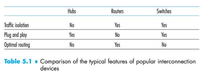
Both switches and routers are candidates for interconnection devices (for network administrators to choose). Pros & Cons↓
Switches
- Switches are plug-and-play;
- Switches have higher filtering and forwarding rates than routers (because switches have to process frames up through layer 2);
- active topology of a switched network is restricted to a spanning tree (to prevent the cycling of broadcast frames);
- a large switched network requires large ARP tables in hosts and routers and would generate substantial ARP traffic and processing.
- switches are susceptible to broadcast storms – if one host goes haywire and transmits an endless stream of Ethernet broadcast frames, the switches will forward all these frames, causing the entire network to collapse. (doubt: this seems contradicts to “advantages of using switches/ease management” in which says switches can detect & disconnect jabbering adapter)
Routers
- topology of network with routers does not have spanning tree restriction (because network addressing is hierarchical, packets do not normally cycle through routers);
hosts connecting to routers need their IP addresses to be configured.
Routers often have a larger per-packet processing time than switches (because they have to process up through layer 3).
When should use switches/routers?
- Switches suffice for small networks (a few hundred hosts), as they localize traffic and increase aggregate throughput without requiring configuration of IP addresses.
- Routers suffice for larger networks (thousands of hosts), because routers provide a more robust isolation of traffic, control broadcast storms, and use more intelligent routes.
VLANs
//need fig 5.15 to illustrate this LAN configuration
Problem: The configuration of “hierarchically configured institutional LANs” (each workgroup has its own switched LAN connected to other groups’ switched LANs via a center switch) has drawbacks --
- Lack of traffic isolation: broadcast traffic has to traverse the entire institutional LAN network; (p.s. can be solved by replacing the center switch with a router, but can also solved by a layer-2 solution – VLANs).
- Inefficient use of switches: If the institution has a large number of groups, the same large number of first-level switches would be required. E.g. 10 level-1 switches are required for 10 small groups.
- Managing users: If a host moves between groups, the physical cabling must be changed to connect the host to a different switch. Hosts belonging to multiple groups is difficult too.
Solution: VLANs.
Virtual local area networks (VLANs): A switch that supports VLANs allows multiple virtual local area networks to be defined over a single physical local area network infrastructure.
Port-based VLAN
In a port-based VLAN, the switch’s ports are divided into groups (by the network manager), each group constitutes a VLAN.
ports in an VLAN form a broadcast domain (broadcast traffic from one port can only reach other ports in the same group). (though these groups share the same physical switch, they are separated logically. Each VLAN’s frames are isolated from another.)
If one user of A group joins another group, the network operator simply reconfigures the VLAN software to associate the port that user is connecting to with VLAN of his new group.
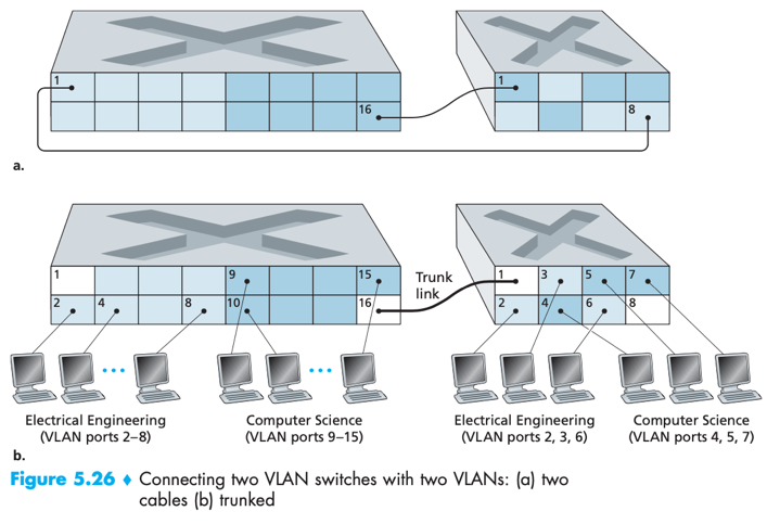
e.g. via VLAN, 2 departments can use the same single switch (port 2~8 for EE, port 9~15 for CS)

How to send traffic across VLANs?
Solution: configure a port (e.g. port 1) as belonging to both VLANs (EE and CS), connect that port to an external router. Datagrams going from VLAN A to VLAN B would goes through the external router (e.g. sender->EE VLAN->router->CS VLAN->receiver).
Nowadays vendors build a single device that contains both a VLAN switch and a router so a separate external router is not needed.
If some members are in separate building, how to add them into their VLAN?
Solution: For a second switch, define some ports as belonging to specific (EE/CS) VLAN as needed.
[connect the two switches]->
a. – easy, doesn’t scale, N VLANs require N ports on each switch.
define a port as belonging to VLAN A (CS) on each switch, similarly for VLAN B (EE), …, etc, connect these ports to each other.
or b. VLAN trunking – more scalable
on each switch, configure a special trunk port to interconnect the two switches. A trunk port belongs to all VLANs, and frames sent to any VLAN are forwarded over the trunk link to the other switch.
-- how does a switch know a frame arriving on a trunk port belongs to a particular VLAN?
-- IEEE defined an extended Ethernet frame format 802.1Q for frames crossing a VLAN trunk, which has an additional VLAN tag (4-byte). VLAN tag is added by switch at sending side of a VLAN trunk and removed by the switch at receiving side of the trunk.

other VLANs -- Besides port, VLANs can also be defined based on MAC address, network-layer protocol, and etc other criteria.
MAC-based VLAN:
network manager specifies a set of MAC addresses that belong to each VLAN. Whenever a device attaches to a port, the port is connected into the appropriate VLAN based on the device’s MAC address.
Link Virtualization
MPLS is a packet-switched, virtual-circuit network, can be virtualized as a link-layer technology (like telephone network, switched-Ethernet) that serves to interconnect IP devices.
MPLS -- a network being considered as a link
Multiprotocol Label Switching (MPLS): blends VC techniques into routed IP datagram network by selectively labeling datagrams and allowing routers to forward datagrams based on fixed-length labels (rather than destination IP addresses).
e.g. a telephone link connecting a home modem/computer to a remote modem/router is actually a path through a sophisticated and complex telephone network.
A link-layer frame transmitted between MPLS-capable devices has a MPLS header added between layer-2 header (Ethernet) and layer-3 header (IP).
Label + reserved for experimental use (3 bits) + S (1 bit, indicates the end of a series of stacked MPLS headers) + time-to-live

MPLS-enhanced frame can only be sent between MPLS-capable routers a.k.a. label-switched router.
An MPLS-capable router forwards an MPLS frame by looking up the MPLS label in its forwarding table then immediately passing the datagram to the appropriate output interface. (thus can route packets without touching their IP headers)
e.g.
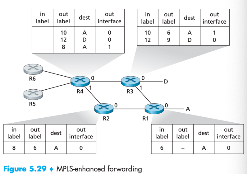
pre: R1~R4 are MPLS capable, R5~6 are standard IP routers.
-> R1 advertised to R2 & R3 that it can route frame with MPLS label 6 to destination A (via interface 0, …etc.);
-> R3 advertised to R4 that it can route frame with MPLS label 10/12 to destination A/D;
-> R2 advertised to R4 that it can route frame with MPLS label 8 to destination A;
-> R4 knows that it can route to destination A via two paths (via R3/via R2), …, etc.
The broad picture: IP devices R5, R6, A and D are connected via an MPLS infrastructure (consists of MPLS-capable routers R1, R2, R3 and R4).
Pros: MPLS provides the ability to forward packets along routes that would not be possible using standard IP routing protocols. E.g. IP routing protocols would specify only a single least-cost path to a destination A, while MPLS provides multiple paths (via R2 or R3).
Data Center Networking
Data center network: Each data center has its own data center network that interconnects its hosts with each other & interconnects the data center with the Internet.
Blades: Hosts in data center that serves content, store documents, collectively perform distributed computations, etc. Blades are stacked in racks.
Top of Rack (TOR) switch: A switch at the top of each rack, interconnects hosts in the rack with each other and with other switches in the data center.
Border routers: connects the data center network to the public Internet data for handling flows between external clients and internal hosts.
Load balancer (a.k.a. layer-4 switch): Inside data center external requests are first directed to a load balancer. A load balancer distributes requests to hosts (and help relay host’ s response back to external client), balancing the load across hosts.
A large data center often has several load balancers, each devoted to a set of specific applications.
Load balancer also provides a NAT-like function (translating public external IP address to appropriate host’s internal IP address, and translate back for reverse direction). –security benefit: hide internal network structure from clients.
Hierarchical Architecture
A data center scaled to tens/hundreds of thousands of hosts often employs a hierarchy of routers and switches.
e.g.

data centers also include redundant network equipment (e.g. access routers, tier-1/2 switches) or links (e.g. between TOR switches and tier-2 switches) to provide applications with availability.
Cons: Conventional hierarchical architecture suffers from limited host-to-host capacity. – If there are many simultaneous flows, the maximum rate between two hosts in different racks can be much less.
1 Possible solution: to deploy higher-rate switches and routers. //expensive cost
-> A trend is to deploy a fully connected topology to replace the hierarchy. e.g.
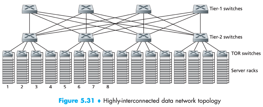
- Each tier-n switch connects to all tier-(n+1) switches thus improve host-to-host capacity.
-> Another trend is to employ shipping container-based modular data centers (MDCs).
--> Factory builds a “mini data center” within a shipping container;
--> ships the container to the data center location,
--> container is designed for graceful performance degradation: as servers/switches fail overtime, the container continues to operate but with degraded performance until having dropped below a threshold and getting replaced.