Chapter 3. Underlying Technologies
// 第三章. 底层技术
We can think of the Internet as a series of backbone networks that are run by international, national, are regional ISPs. The backbones are joined together by connecting devices such as routers or switching stations. The end users are either part of the local ISP LAN or connected via point-to-point networks to the LANs. Conceptually, the Internet is a set of switched WANs (backbone). LANs, point-to-point WANs, and connecting or switching devices.
Although the TCP/IP Protocol Suite is normally shownas five-layer stack, it only defines the three upper layers: TCP/IP is only concerned with the network, transport, and application layers. This means that TCP/IP assumes the existence of these WANs, LANs, and the connecting devices that join them.
As a brief review, we touch upon some of these underlying technologies in this chapter.
// 我们能够把因特网想为网络的骨干, 包括全球的、国家的、地区的ISP。 骨干被连接在一起通过相关设备诸如路由器和交换机站点。
OBJECTIVES
The chapter has several objectives:
- To briefly discuss the technology of domainant wired LANs, Ethernet, including traditional, fast, gigabit, and ten-gigabit Ethernet.
- To briefly discuss the technology of wireless WANs, including IEEE 802.11 LANs, and Bluthtooth.
- To briefly discuss the technology of point-to-point WANs including 56K modems, DSL, cable modem , T-lines, and SONET.
- To briefly discuss the technology of switched WANs including X.25, Frame Relay, and ATM.
- To discuss the need and use of connecting devices such as repeaters (hubs), bridges (two-layer switches), and routes (three-layer switches).
3.1 WIRED LOCAL AREA NETWORKS
A local area network (LAN) is a computer network that is designed for a limited geographic area such as a building or a campus. Although a LAN can be used as an isolated network to connect computers in an organization for the sole purpose of sharing resources, most LANs today are also linked to a wide area network (WAN) or the Internet.
The LAN market has seen several technologies such as Ethernet, token ring, token bus, FDDL, and ATM LAN. Some of these technologies survived for a while, but Ethernet is by far the dominant technology.
In this section, we first discuss the IEEE standard Project 802, designed to regulate the manufacturing and interconnectivity between different LANs. We then concentrate on the Ethnet on the Ethernet LANs.
Although Ethernet has gon through a four-generation evolution during the last few decdes, the main concept has remained the same. Ethernet has changed to meet the market needs and to make use of the new technologies.
IEEE Standards
In 1985, the Computer Society of the IEEE started a project, called Project 802, to set standards to enable intercommunication among equipment from a variety of manufacturers. Project 802 does not seek to replace any part of the OSI or the Internet model. Instead, it is a way of specifying functions of the physical layer and the data link layer of major LAN protocols.
The standard was adopted by the American National Standards Institute (ANSI). In 1987, the International Standards Organization (ISO) also approved it as international standard under the designation ISO 8802.
The relationship of the 802 Standard to the traditional OSI model is shown in Figure 3.1. The IEEE has subdivided the data link layer into two sublayers: logical link control (LLC) and media access control (MAC). IEEE has also created several physical layer standards for different LAN protocols.
Figure 3.1 IEEE stand for LANs
| LLC: logical link control | Data link layer | LLC | ||||||
| Ethernet MAC | Token ring MAC | Token bus MAC | ||||||
| MAC: Media access control | physical layer | Ethernet physical layers | Token ring physical layers | Token bus physical layer | ||||
| Transmission medium | Transmission medium | |||||||
| OSI or TCP/IP Suite | IEEE Standard | |||||||
In this text, however, we treat physical and data link layer together as the underlying technology supporting other layers in the TCP/IP protocol suite. For more details about physical and data link layer technology see Forouzan, Data Communications and Networking, 4th ed., MCGraw-Hill, 2007.
Frame Format
The packet sent in an Ethernet LAN is called a frame. In this section we discuss the format and the length of the frame that is used in our versions of the Ethernet.
Frame Format
The Ethernet frame contains seven fields: preamble, SFD, DA, SA, length or type of data unit, upper-layer data, and the CRC. Ethernet does not provide any mechanism for acknowledging received frames, making it what is known as an unreliable medium. Acknowledgments must be implemented at the higher layers. The format of the MAC frame is shown in Figure 3.2.
Figure 3.2 Ethernet frame
| Premble: 56 bits of alternating 1s and 0s. | ||||||||
| SFD: Start frame delimiter, flag (10101011) | ||||||||
| ▅ | Preamble | SFD | Destination address | Source address | Length or type | Data and padding | CRC | |
| 7 bytes | 1 bytes | 6 bytes | 6bytes | 2 bytes | 4 bytes | |||
| Physical layer header | ||||||||
- Preamble. The first of the 802.3 frame contains 7 bytes (56 bits) of alternating 0s and 1s that alerts the receiving system to coming frame and enables it to synchronize its input timing. The pattern provides only an alert and a time pulse. The 56-bit pattern allows the stations to miss more bits at the beginning of the frame. The preamble is actually added at the physical layer and is not (formally) part of the frame.
- Start frame delimiter (SFD). The second field (1 byte: 10101011) signals the beginning of the frame. The SFD warns the station or stations that this is the last chance for synchronization. The last 2 bits are 11 and alert the receiver that the next field is the destination address. The SFD is also added at the physical layer.
- Destination address (DA) . The DA field is 6 bytes and contains the physical address of the destination station or stations to receive the packet. We will discuss addressing shortly.
- Source address (SA). The SA field is also 6 bytes and contains the physical address of the sender of the packet.
- Length or type. This field is defined as a type field or length field. The original Ethernet used this field as the type field to define the upper-layer protocol using the MAC frame. The IEEE standard used it as the length field to define the number of bytes in the data field. Both uses are common today.
- Data. This field carries data encapsulated from the upper-layer protocols. It is a minimum of 46 and a maximum of 1500 bytes, as we will see later.
- CRC. The last field contains errors detection information, in this case a CRC-32 (See Appendix C)
Frame Length
Ethernet has imposed restrictions on both the minimum and maximum lengths of a frame, as shown in Figure 3.3
Figure 3.3 Minimum and maximum Lengths
| Minmum payload length: 46bytes | |||||
| Maximum payload length:1500 bytes | |||||
| Destination address | Source address | Legth or Type | Data and padding | CRC | |
| 6 bytes | 6 bytes | 2 bytes | 4 byte | ||
| Minimum frame length: 512 bits or 64 bits | |||||
| Maximum frame length: 12,144 bits or 1518 bytes | |||||
The minimum length restriction is required for the correct operation of CMSA/CD, as we will see shortly. An Ethernet frame needs to have a minimum length of 512 bits or 64 bytes. Part of this length is the header and the trailer. If we count 18 bytes of header and trailer (6 bytes of source address, 6 bytes of destination address, 2 bytes of length or type, and 4 bytes of CRC ), then the minimum length of data from the upper layer is 64-18=46 bytes. If the upper-layer packet is less than 46 bytes, padding is added to make up the difference.
The standard defines the maximum length of a frame (without preamble and SFD field) as 1518 bytes. If we subtract the18 bytes of the header and trailer, the maximum length of the payload is 1500 bytes. The maximum length restriction has two historical reasons. First, memory was very expensive when Ethernet was designed: a maximum length restriction helped to reduce the size of the buffer. Second, the maximum length restriction prevents one station from monopolizing the shared medium, blocking other station that have data to send.
Minimum length: 64bytes (512 bits) Maximum length: 1518 bytes (12,144 bits)
Addressing
Each station on an Ethernet network (such as a PC, workstation, or printer) has its own network interface card (NIC). The NIC fits inside the station and provides the station with a 6-byte physical address. As shown in Figure 3.4, the Ethernet address is 6 bytes (48 bits), normally written in hexadecimal notation, with a colon between the bytes. The address normally is referred to as the data link address, physical address, or MAC address.
Figure 3.4 Ethernet address in hexadecimal notation
| d: Hexadecimal digit | |
| d1 d2 : d3d4 : d5 d6 : d7 d8 : d9 d10 : d 11 d12 | |
| 6 bytes = 12 hexadecimal digital = 48 bits | |
For example, the following shows an Ethernet MAC address:
4A:30:10:21:10:1A
Unicast, Multicast, and Broadcast Addresses
A source address is always a unicast address -- the frame comes from only one station. The destination address, however, can be unicast, multicast, or broadcast. Figure 3.5 shows how to distinguish a unicast address from a multicast address. If least significant bit of the first byte in a destination address is 0, the address is unicast, otherwise it is multicast.
Figure 3.5 Unicast and multicast address
The least significant bit of the first byte defines the type of address. If the bit is 0 , the address is unicast; otherwise, it is multicast.
A unicast destination address defines only one recipient; the relationship between the sender and the reciever is one-to-one. A multicast destination address defines a group of address; the relationship between the sender and the receivers is one-to-many.
The broadcast address is a special case of the multicast address; the recipients are all the stations on the LAN. A broadcast destination address is forty-eight 1s.
The broadcast destination address is a special case of the multicast address in which all bits are 1s.
Example 3.1
Define the type of the following destination addresses:
a. 4A:30:10:21:10:1A
b. 47:20:1B:2E:08:EE
c. FF:FF:FF:FF:FF:FF
Solution
To find the type of the address, we need to look at the second hexadecimal digit from the left. If it is even, the address is unicast. If it is odd, the address is multicast. If all digitals are F's, the address is broadcast. Therefore, we have the following:
a. This is a unicast address because A in binary is 1010 (even).
b. This is a multicast address because 7 in binary is 0111(odd)
The way the addressese are sent out on line is different from the way they are written in hexadecimal notation. The transmission is left-to-right, byte by byte; however, for each byte, the least significant bit is sent first and the most significant bit is sent last. This means that the bit that defines an address as unicast or multicast arrives first at the receiver.
Example 3.2
Show how the address 47:20:1B:2E:08:EE is sent out in line.
solution
The address is sent left-to-right, byte-to-byte; for each byte, it is sent right-to-left, bit by bit, as shown below
| ← | 1110,0010 | 0000,0100 | 1101,1000 | 01110100 | 00010000 | 01110111 |
| 0100,0111 | 0010,0000 | 0001,1011 | 00101110 | 00001000 | 11101110 | |
| 47 | 20 | 1B | 2E | 08 | EE |
Ethernet Evolution
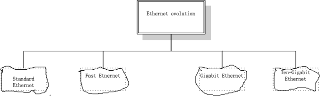
Ethernet was created in 1976 at Xerox's Palo Alto Research Center (PARC). Since then it has gone through four generations: Standard Ethernet (10 Mbps), Fast Ethernet (100 Mbps), Gigabit Ethernet (1 Gbps), and Ten-Gigabit Ethernet (10 Gbps), as shown in Figure 3.6. We briefly discuss all these generations staring with the first, Standard (or traditional) Ethernet.
Figure 3.6 Ethernet evolution through four generations
Standard Ethernet
The original Ethernet with 10-Mbps data rate is now history, but we briefly discuss its characteristics to pave the way for understanding other Ethernet versions.
Access Method :CSMA / CD
// 访问方法 : CSMA /CD (载波监听多路访问技术)
The IEEE 802.3 standard defines: carrier sense multiple access with collision detection (CSMA / CD) as the access method for traditional Ethernet. Stations on a traditional Ethernet can be connected together using a physical bus or star topology, but the logical topology is a bus. By this, we mean that the medium (channel) is shared between stations and only one station at a time can use it. It also implies that all stations receive a frame sent by a station (broadcasting). The real destination keeps the frame while the rest drop it. In this situation, how can we be sure that two stations are not using the medium at the same time? If they do, their frames will collide with each other.
// IEEE 802.3 标准定义了:对于传统的Ethernet访问方法是 CSMA/CD 。 在传统Ethernet 上的站点可以被连接起来使用一条物理总线或者星型拓扑, 但是逻辑拓扑是一条总线。到此为止, 我们明的了,媒介(信道) 是被多个站点共享的, 并且仅仅一个站点在某一刻能够使用它。 它也暗示了, 所有的站点接收到了来自同一站点的帧(广播)。真正的目的地址保留相对应的帧,当其它的站点放弃这个目标。 在这种情况下,我们怎么能够确保两个站点在同一时间段没有使用媒介。 如果他们同时使用,他们的帧将彼此冲突。
( Sense /sens / n. 感知;
collision /kəˈlɪʒ.ən / n. a strong disagreement 冲突;抵触;
medium /ˈmiː.di.əm/ n. 媒介方法;
channel /ˈtʃæn.əl/ n. 信道;
collide /kəˈlaɪd/ vt. (especially of moving objects) to hit something violently. (尤指移动的物体) 相撞、相碰;
)
To minimize the chance of collision and, therefore, increase the preformance, the CSMA method was developed. The chance of collision can be reduce if a station sensens the medium before trying to use it. Carrier sense multiple access (CSMA) requires that each station first listen to the medium (or check the state of the medium) before sending. In other words, CMSA is based on the principle "sense before transmit" or "listen before talk". CSMA can reduce the possiblity of collision, but it cannot eliminate it. The reason for this is shown in Figure 3.7, a space and time model of a CSMA network. Stations are connected to a shared channel (usually a dedicated medium).
// 为了最小化冲突的机会, 因此,增加性能,CSMA 方法被开发出来。如果一个站点在准备使用媒介之前能够感知到媒介,那么冲突的机会能够被降低。 载波监听多路访问技术需要, 每个站点在发送帧之前首先监听媒介(亦或检查媒介状态)。 换句话说, CMSA 是基于这样的原理:“传输前感知”或者“说前先听”。 CSMA 能够减少冲突的可能性, 但是它不能排除这种冲突。 如图3.7 所示的原因, CSMA 网络的时空模型, 站点被连接起来通过一条共享信道(通常是一条专用的媒介)。
( eliminate /iˈlɪm.ɪ.neɪ/ vt. to remove or take away someone or something 排除, 消除, 清除
dedicated /ˈded.ɪ.keɪ.tɪd/ n. designed to be used for a particular purpose 专用的;专门的)
Figure 3.7 Space / time model of a collision in CSMA.
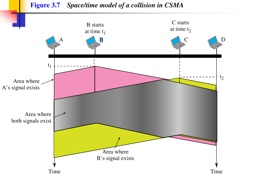
The possibility of collision still exists because of propagation delay; when a station sends a frame; it still takes time (although very short) for the first bit to reach every station and for every station to sense it. In other words, a station may sense the medium and find it idle, only because the first bit sent by another station has not yet been received.
//冲突仍然存在,原因是传播延时;当一个站点发送一个帧, 当一个站点发送一个帧时, 它仍然需要时间(尽管非常短)去发送第一个比特到每一个站点, 并且每一个站点还得侦听它。 换句话说, 一个站点可能侦听媒介并且发现媒介空闲,仅仅是因为被另外一个站点发送首位比特还没有被接收到。
( propagation /,prɒpə'ɡeɪʃən/ n . to spread opinions, lies, or beliefs among many people. 传播;
idle/ ˈaɪ.dəl/ adj. An idle moment or period of time is one in which there is no work or activity空闲的; )
At time t1 , station B sense the medium and finds it idle, so it sends a frame. At time t2 (t2 >t1), station C sense the medium and find it idle because, at this time, the first bits from station B have not reached station C. Station C also sends a frame. The two signals collide and both frames are destroyed.
// 在时间点t1 , 站点A 侦测媒介,并且发现它闲置,因此就发送了一帧。 在时间点t2 (t2 >t1) , 站点C 侦测媒介,并且发现它闲置,因为,在这一时间段, 来自站点B的首位比特还没有到达站点C。 站点C 也发送了一帧。两个信号冲突并且两个帧都被破坏。
Carrier sense multiple access with collision detection (CSMA / CD) aguments the algorithm to handle the collision. In this method, a station monitors the medium after it sends a frame to see if the transmission was successful. If so, the station is finish. If, however, there is a collision, the frame is sent again. To better understand CSMA/CD, let us look at the first bits transmitted by the two stations involved in the collision. Although each station continues to send bits in the frame until it detects the collision, we show what happens as the first bits collide. In Figure 3.8, station A and C are involved in the collision.
// 带冲突检查的载波监听多路访问技术增加算法处理冲突。 用这种方法,一个站点先发送一帧后监控媒介,看,是否传输成功, 如果成功,站点是完成。 如果无论如何,有冲突,帧再一次被发送。 为了更好地理解CSMA/CD, 让我们看在两个站点间传输的首个比特位涉及在冲突域中。尽管每一个站点直到侦测到冲突时,以帧的形式持续发送比特位,我们要显示的是作为第一比特位冲突发生了什么。 在图3.8中,站点A 和站点C被涉及在一个冲突中。
(agument /ɔːɡˈment/ vt. to increase the size or value of something by adding something to it 增加 )
Figure 3.8 Collision of the first bit in CSMA / CD
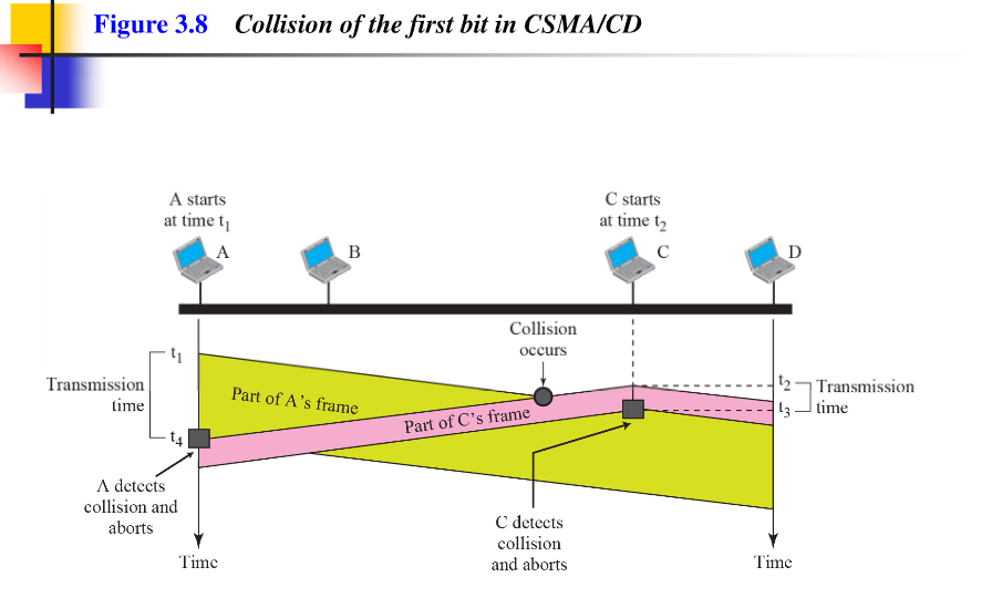
At time t1 , station A has started sending the bits of its frame. At time t2 , station C has not yet sensed the first bit sent by A. Station C starts sending the bits in its frame, which propagate both to the left and to the right. The collision occurs sometime after time t2 . Station C detects a collision at time t3 when it receives the first bit of A's frame. Station C immediately (or after a short time, but we assume immediately) aborts transmission. Station A detects collision at time t4 when it receives the first bit of C's frame; it also immediately aborts transmission. Looking at the figure, we see that A transmits for the duration t4 - t1; C transmits for the duration t3 - t2 . Later we show that, for the protocol work, the length of any frame divided by the bit rate in this protocol must be more than either of these duration. At time t4 , the transmission of A's frame, though incomplete, is aborted; at time t3 , the transmission of B's frame, through incomplete, is aborted. // 在时间点 t1 时, 站点A 已经开始以帧的形式发送比特位。 在时间点 t2 时, 站点C还没有侦测到由站点A 发送的首个比特位。 站点C 开始以帧的形式发送比特,并且开始向左和向右双向传播。冲突发生在时间节点t2 . 站点C 在时间节点t3探测到冲突, 当它接收到A站的帧的首位地址。站点C立即(或者一个短时间段后,但是我们假设立即)中止传输。当站点A接收到站点C发送帧的首位比特时,它在时间节点4侦测到冲突;它也立即中止传输。 仔细看图, 我们看见 站点A 传输持续时间为 t4 - t1; 站点脚传输持续时间为 t3 - t2 . 再往后看, 依据协议运转,任何帧的长度除以该协议的比特速率的商必须大于这些时间段中的任何一个。 在时间节点t4 , A的帧的传输,尽管没有完成,但是中止了;在时间节点t3, B的帧的传输,尽管没有完成,但是中止了。
( detect /dɪˈtekt/ vt. to notice something that is partly hidden or not clear, or to discover something, especoially used a special method. (尤指用特殊的方法)发现,察觉,看出
abort /əˈbɔːt/ vt. to case something to stop or fail before it begins or before it is complete. 中止;使夭折,使中途失败。
duration /djʊəˈreɪ.ʃən/ n. the length of time that something lasts. 持续时间
protocol /ˈprəʊ.tə.kɒl / n. a formal international agreement. (正式的国际性)条约、协议书、公约
incomplete /ˌɪn.kəmˈpliːt/ adj. not having some parts, or not fished 不完整的,未完成的;)
Minimum Frame Size
For CSMA / CD to work, we need a restriction on the frame size. Before sending the last bit of the frame, the sending station must detect a collision, if any, and abort the transmission. This is so because the station, once the entire frame is sent, does not keep a copy of the frame and does not monitor the line for collision detection. Therefore, the frame transmission time Tfr must be least two times the maximum propagation time Tp . To understand the reason, let us think about the wrost-case scenario. If the two stations involved in a collision are the maximum distance apart, the signal from the frist takes time TP to reach the second, and the effect of the collision takes another time Tp to reach the first. So the requirement is that the first station must still be transmitting after 2TP .
Example 3.3
In the standard Ethernet, if the maximum propagation time is 25.6μs, what is the minimum size of the the frame?
Solution
The frame transission time is Tfr = 2 × TP = 25.6μs ×2 = 51.2μs. This means, in worst case, a station needs to transmit for a period of 51.2 μs to detect the collision. The minimum size of the frame is 10 Mbps×51.2μs =512bit or 64 bytes. This is actually the minimum size of the frame for Standard Ethernet, as we discussed before.
// 最小帧尺寸
对于CSMA/CD的运行, 我们在帧的尺寸大小需要有一定的限制。在发送特定帧的最后一位比特前,发送站点必须侦测冲突,如果存在任何一个,那么中止传输。 这就是,因为站点,一旦一个帧的全部被发送,不保留这个帧的副本,也不监控线上的冲突侦察。因此,帧的传输时间TFR 必须至少是最大传输时间Tp的两倍。 去理解这个原因,让我们想一个最糟糕的例子。 如果两个站点涉及一个冲突是在最远距离之外, 来自第一个站点的们号到达另一个站点的时间为Tp , 冲突响应到第一站点所需时间Tp 。 因此对于第一站点的需求必须在两个Tp 时间间隔后仍在传输。
示例3.3
在标准的以太网中,如果最大传输时间是25.6μs,帧的最小尺寸是多大?
解答:
帧的传输时间是51.2μs , 这意味着,在最糟糕的情况下,一个站点必须用51.2 μs的时间段去探测冲突传输。帧的最小尺寸是512位或者64字节。这是标准以太网精确的最小尺寸,正如我们前边的讨论。
(scenario /sɪˈnɑː.ri.əʊ/ n. a description of possible actions or events in the future.可能发生的事态,设想。 )
Procedure
// 流程
(procedure /prəˈsiː.dʒər/ n. a set of actions that is offical or accepted way of doing something . 程序,步骤,常规)
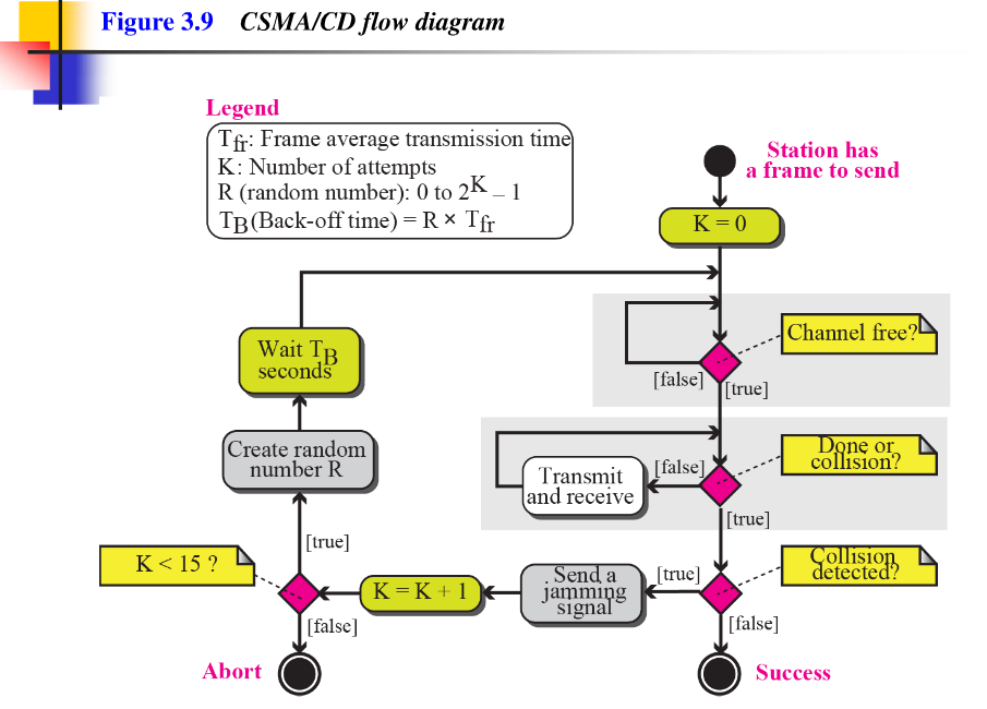
Figure 3.9 shows the flow diagram for CSMA / CD. We need to sense the channel before we start sending the frame. We do not send the entrie frame and then look for a collision. The station transmits and receives continuously and simultaneoudly (using two different ports). We use a loop to show that transmission is a continuous process. We constantly monitor in order to detect one of two conditions: either transmission is finished or a collision is detected. Either event stops transmission. When we come out of the loop, if a collision has not been detected, it means that transmission is complete; the entire frame is transmitted. Otherwise, a collision has occurred. The diagram also shows a short jamming signal that enforces the collision in case other stations have not yet sensed the collision.
// 图3.9 所示为CSMA / CD 的流程图, 我们在开始发送帧之前需要对信道进行监听。我们并没有发送完整的帧去寻找一个冲突。 站点持续传输,并同时接收 (使用两个不同的接口)。 我们使用一个循环去显示一个持续的过程。 我们一直监控目的是去探测两个条件中的一个:传输完成或者冲突被侦测到。 两件事件中之一都停止传输。 当没有冲突被侦测出来的时候,我们就跳出循环,也就意味着传输成功,整个帧被传输。相反,一个冲突已经发生。 该图也显示了一个短的干扰信号,在其他站还没有检测到碰撞的情况下强制执行碰撞。
Figure 3.9 CSMA /CD flow diagram.
Implementation
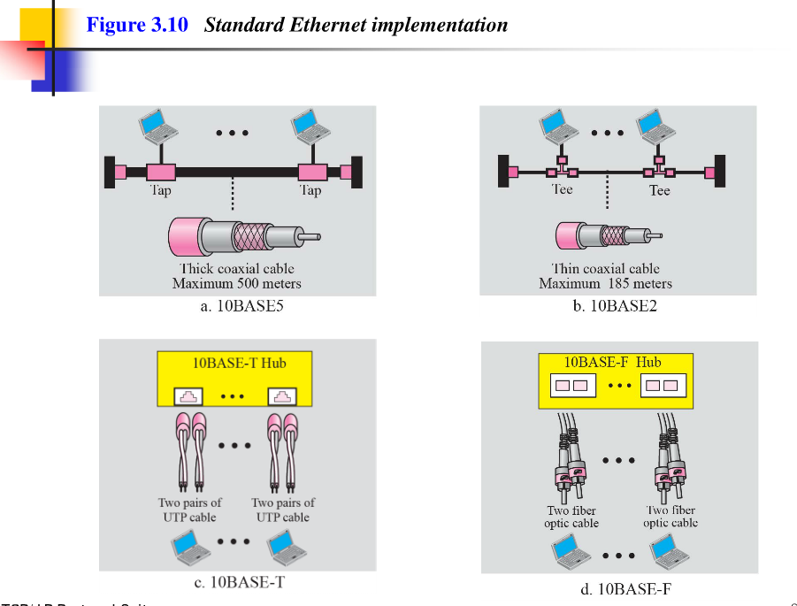
The standard Ethernet defined several implementations, but only four of them because popular during '80s. Table 3.1 shows a summary of Standard Ethernet implementations. In the nomenclature 10Base-X, the number defines the data rate (10 Mbps), the term Base means baseband (digital) signal, and X approximately defines either the maximum size of the cable in 100 meters (for example 5 for 500 or 2 for 185 meters) or the type of the cable, T for unshielded twisted pair cable (UTP) and F for fiber-optic.
Table 3.1 Summary of Standard Ethernet implementations
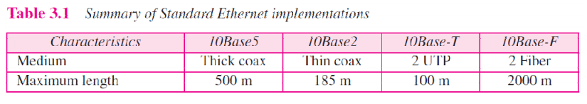
Figure 3.10 Show simplified diagrams of each implementation.
Fast Ethernet
// 快速以太网
Fast Ethernet was designed to complete with LAN protocols such as FDDI or Fiber Channel. IEEE created Fast Ethernet under the name 802.3u. Fast Ethernet is backward-compatible with Standard Ethernet, but it can transmit data 10 times faster at a rate of 100 Mbps. The goals of Fast Ethernet can be summarized as follows:
- Upgrade the data rate to 100 Mbps.
- Make it compatible with Standard Ethernt.
- Keep the same 48-bit address.
- Kepp the same frame format.
- Keep the same minimum and maximum frame lengths
// 快速以太网的设计是符合LAN协议,例如FDDI 或者 光纤信道。 IEEE 创建快速以太网以802.3的名义命名。 快速以太网完成后至兼容传统以太网,但是它传输数据提高了10倍,以100Mbpd的速度传输。以太网的目标被宗述如下:
- 升级数据速率至100Mbps。
- 与传统以太网完全兼容。
- 保持同样的48位地址。
- 保持同样的帧格式。
- 保持帧同样的大小长度。
MAC Sublayer
// MAC子层
A main consideration in the evolution of Ethernet from 10 to 100 Mbps was to keep the MAC sublayer untouched. However, a decision was made to drop the bus topologies and keep only the star topology. For the star topology, there are two choices: half deplex and full deplex。 In the half-duplex approach, the stations are connected via a hub; in the full-duplex approach, the connection is made via a switch with buffers at each port (See Section 3.5, Connecting Devices, at the end of the chapter).
The access method is the same (CSMA / CD) for the half-duplex approach; for full-duplex Fast Ethernet, there is no need for CSMA / CD. However, the implementations Keep CSMA / CD for backward compatibility with Standard Ethernet.
// 以太网从10Mbps 到100Mbps的变革过中,主要考虑的是MAC子层不触碰。 无论如何,下定决心丢掉总线拓扑,保留星型拓扑。 对于星型拓扑,存在两种选择:半工和全双工。 在半工方式中,站点被连接通过hub, 在全双工方式中,通过一个交换机与每个站口上的缓冲区建立连接(参看3.5节,连接设备,在本章末)
对于半双工方式,其访问方式与(CSMA / CD )是相同的;对于全双工快速以太网, 不需要CSMA/CD。 无论如何,实现后至兼容传统以太网保留了CSMA/CD。
(buffer //ˈbʌf.ər/ v. When a computer buffers information or buffers, it stores information temporarily in its memory while dealing with it and sending it (计算机缓存于内存中))
Autonegotiation
//自动协商机制
(auto-negotiation /nəˌɡəʊ.ʃiˈeɪ.ʃən/ n. Autonegotiation is an Ethernet procedure by which two connected devices choose common transmission parameters, such as speed, duplex mode, and flow control. In this process, the connected devices first share their capabilities regarding these parameters and then choose the highest performance transmission mode they both support. 自动协商机制是一种以太网流程:两个相连设备选择相同的传输限定因素:例如速度、双工模式和流控制。 在这个过程中,被连接的设备首先分享他们关于这些参数的能力,然后选择它们都支持的最高性能传输模式。)
A new feature added to Fast Ethernet is called autonegotiation. It allows a station or a hub a range of capabilities. Autonegotiation allows two devices to negotiate the mode or data rate of operation. It was designed particularly for the following purposes:
- To allow incompatible devices to connect to one another. For example, a device with a maximum capacity of 10 Mbps can communication with a device with a 100 Mbps capacity (but can work at a lower rate)
- To allow one device to have multiple capabilities.
- To allow a station to check a bub's capabilities.
// 以太网新增的符加功能,被称作自动协商机制。 它认同站点和集线器的一系列性能参数。 自动协商机制允许两台设备协商操作模式和数据速率。 它是专门为以下目的设计的。
- 允许相互不兼容的设备相连接。 例如一台速率参数值为10Mbps的设备能够屯一台100Mbps的设备相连接(但是能够运作以较低的速率)
- 允许一台设备具有多种功能。
- 允许一个站点可以检查集线器的功能参数。
Implementation
Fast Ethernet implemenation at the physical layer can be categorized as either two-wire or four-wire. The two-wire implementation can be either shielded twisted pair, STP(100Base-Tx) or fiber-optic cable (100 Base-Fx). The four-wire implementation is designed only for unshielded twist pair, UTP (100Base-T4). Table 3.2 is a summary of the Fast Ethernet implementations.
//快速以太网在物理层的实现既可以按双导线或也可以按四导线两种来分。 双线制实现也可以是屏蔽双绞线, STP(100Base-TX) 或者光缆(100Base-FX)。 四线制实现的实现仅仅是为了非屏蔽双绞线, UTP(100Base-T4)。 表3.2 总结了快速以太网的实现。
( shield /[ʃiːld/ n. something or someone used as protection or providing protection 保护物,屏障,保护者; 计算机专业:屏蔽;
twist /twist/ n. 双绞线
fiber/ 'faɪbɚ/ n. 光纤
optic ['ɒptɪk/ adj. 光学的;
wire /waɪə/ n. 导线 )
Table 3.2 Summary of Fast Ethernet implementation.
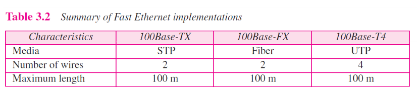
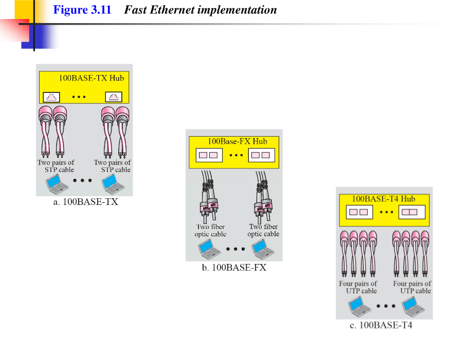
Figure 3.11 Summary of Fast Ethernet implementation
Gigabit Ethernet
The need for an even higher data rate resulted in design of the Gigabit Ethernet Protocol (1000Mbps). The IEEE committee calls the Standard 802.3z. The goals of the Gigabit Ethernet design can be summarized as follows:
- Upgrade the data rate to 1Gbps.
- Make it compatible with Standard or Fast Ethernet.
- Use the same 48-bit address.
- Use the same frame format.
- Keep the same minimum and maximum frame lengths.
- To support autonegotiation as define in Fast Ethernet.
MAC sublayer
A main consideration in the evolution of Ethernet was keep the MAC sublayer untouched. However, to achieve a data rate of 1 Gbps, this was no longer possible. Gigabit Ethernet has two distinctive approaches for medium access: half-duplex and full-deplex. Almost all implementations of Gigabit Ethernet follow the full-duplex approach. However, we briefly discuss the half-duplex approach to show that Gigabit Ethernet can be compatible with the previous generations.
Full-Deplex mode
In full-deplex mode, thereis a central switch connected to all computers or other switches. In this mode, each switch has buffers for each input port in which data are stored until they are transmitted. There is no collision in this mode. This means that CSMA/CD is not used. Lack of collision implies that the maximum length of the cable is determined by the signal attenuation in the cable, not by the collision detection process.
In the full-duplex mode of Gigabit Ethernet, there is no cillision; the maximum length of the cable is determined by the signal attention in the cable.
Half-Duplex mode
Gigabit Ethernet can also be used in half-duplex mode, although it is rare. In this case, a switch can be replaced by a hub, which acts as the common cable in which a collision might occur. The half-duplex approach uses CSMA/CD. However, as we saw before, the maximum length of the network in this approach is totally dependent on the the minimum frame size. Three solutions have been defined: traditional, carrier extennsion, and frame bursting.
- Traditional. In the traditional approach, we keep the minimum length of the frame as in traditional Ethernet (512 bits). However, because the length of a bit is 1/100 shorter in Gigabit Ethernet than in 10-Mbps Ethernet, the maximum length of the network is 25m. This length may be suitable if all the stations are in one room, but it may not even be long enough to connect the computers in single office.
- Carrier Extension. To allow for a longer network, we increase the minimum frame length. The carrier extension approach defines the minimum length of a fram as 512 bytes(4096 bits). This means that the minimum length is 8 times longer. This method forces a station to add extension bits (padding) to any frame that is less than 4096 bits. In this way, the maximum length of the networkcan be increased 8 times to a length of 200 m. This allows a length of 100 m from the bub to the station.
- Frame Bursting. Carrier extension is very inefficient if we have a series of short frames to send; each frame carries redundant data. To improve efficiency, frame bursting was proposed. Instead of adding an extension to each frame, multiple frames are sent. However, to make these multiple frames look like one frame, padding is added between the frames ( the same as that used for the carrier extension methold ) so that the channel is not idle. In other words, the method deceives other stations into thinking that a very large frame has been transmitted.
Implementation
Table 3.3 is a summary of the Gigabit Ethernet implemenations
Table 3.3 Summary of Gigabit Ethernet implementaion
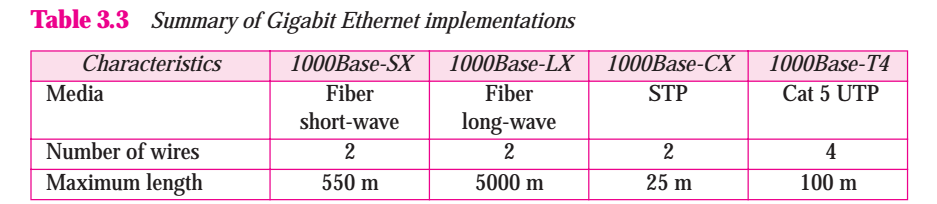
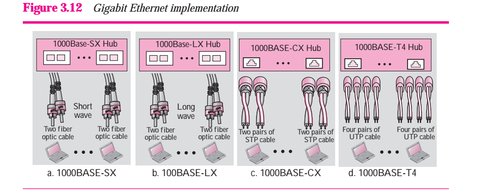
Figure 3.12 shows the simiplified diagrams for Gigabit Ethernet
Ten-Gigabit Ethernet
The IEEE commitee created Ten-Gigabit and called it Standard 802.3ae. The goals of the Ten-Gigabit Ethernet design can be summarized as follows:
- Upgrade the data rate to 10 Gbps.
- Make it compatible with Standard. Fast, and Gigabit Ethernet.
- Use the same 48-bit address.
- Use the same frame format.
- Keep the same minimum and maximum frame length.
- Allow the interconnection of existing LANs into a metropolitan area network (MAN) or a wide area network (WAN)
- Make Ethernet compatible with technologies such as Frame Relay and ATM.
Implementation
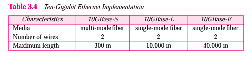
Ten-Gigabit operates only in full duplex mode, which means there is no need for contention: CSMA/CD is not used in Ten-Gigabit Ethernet. Three implementations are the most common: 10 GBase-S, 10GBase-E. Table 3.4 shows a summary of the Ten-Gigabit Ethernet implementation.
Table 3.4 Ten-Giagabit Ethernet Implementation
3.2 WIRELESS LANS
Wireless communication is one of the fastest-growing technologies. The demand for connecting devices without the use of cables is increasing everywhere. Wireless LANs can be found on college campuses, in office buildings, and in many pubic areas. In this section, we concentrate on two wireless technologies for LANs: IEEE 802.11 wireless LANs, sometimes called wireless Ethernet, and Bluthtooth, a technology for small wireless LANs.
IEEE 802.11
IEEE has defined the specifications for a wireless LAN, called IEEE 802.11, which covers the physical and data link layers.
Architecture
The standard defines two kinds of services: the Basic service set (BSS) and the extended services set (ESS).
Basic Services Set
IEEE 802.11 defines the basic service set (BSS) as the building block of a wireless LAN. A basic service set is made of stationry or mobile wireless stations and an optional central base station, known as the access point (AP). Figure 3.13 shows two set in this standard. The BSS without an AP is a stand-alone network and cannot send data to other BBSs. It is called an ad hoc architecture. In this architecture stations can form a network without the need of an AP; they can locate one another and agree to be part of a BSS. A BSS with an AP is sometimes referred to as an infrastructure network.
Figure 3.13 Basic service sets (BSSs)

Extended Service Set
An extended service set (ESS) is made up of two or more BSSs with APs. In this case, the BSSs are connected through a distribution system, which is usually a wired LAN. The distribution system connects the APs in the BBSs. IEEE 802.11 does not restrict the distribution system; it can be any IEEE LAN such as an Ethernet. Note that the extended service set uses two types of stations: mobile and stationary. The mobile stations are normal stations inside a BSS. The stationary stations are AP stations that are part of a wired LAN. Figure 3.14 showes as ESS.
Figure 3.14 Extened services sets (ESSs)
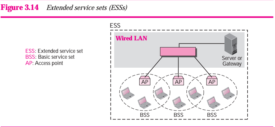
When BBS are connected, the stations within reach of one another can communicate without the use of an AP. However, communication between two stations in two different BSSs usually occurs via two APs.
Station Types
IEEE 802.11 defines three typed of stations based on their mobility in a wireless LAN: no-transition, BSS-transition, and ESS-transition mobility. A station with no-transition mobility is either stationary ( not moving ) or moving only inside a BSS. A station with BSS-transition mobility can move from one BBS to another, but the movement is confined inside one ESS. A station with ESS-transition mobility can move from one ESS to another.
MAC Sublayer
There are two different MAC sublayers in this protocol, however, the one that is used most of the time is based on CSMA/CA (Carrier sense multiple access with collision avoidance). Figure 3.15 shows the flow diagram.
Figure 3.15
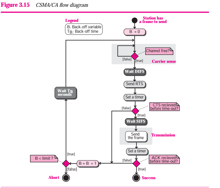
Wireless LANs cannot implement CSMA / CD for three reasons:
- For collision detection must be able to send data and receive collieion signals at the same time. This can mean costly stations and increased bandwidth requirements.
- Collision may not be detected because of the hidden stations problem. We will discuss this problem later in the chapter.
- The distance between stations can be great. Signal fading could prevent a station at one end from hearing a collisioning at the other end.
Frame Exchange Time Line
Figure 3.16 shows the exchange of data and control frames in time
Figure 3.16 CSMA/CA and NAV

1. Before sending a frame, the source station sense the medium by checking the energy level at the carrier frequency.
a. The channel uses a persistence strategy with back-off unitl the channel is idel.
b. After the station is found to be idel, the station waits for a period of time called the distributed interframe space (DIFS);then the station sends a control frame called the request to send (RTS)
2. After receiving the RTS and waiting a period of time called the short interframe space (SIFS), the destination station sends a control frame, called the clear to send (CTS), to the source station. This control frame indicates that the is ready to receive data.
3. The source station sends data after waiting an amount of time equal to SIFS.
4.The destination station, after waiting an amount of time equal to SIFS, sends an acknowledgment to show that the frame has been received. Achnowledgment is needed in this protocol because the station does not have any means to check for the successful arrival of its data at the destionation. On the other hand, the lack of collision in CSMA / CD is kind of indication to the source that data have arrived.
Network Allocation Vector
How do other stations defer sending their data if one station acquires access? In other words, how is the collision avoidance aspect of this protocol accomplished? The key is a feature called NAV.
When a station sends an RTS frame, it cludes the duration of time that it needs to occupy the channel. The stations that are affected by this transmission create a timer called a network allocation vector (NAV) that shows how much time must pass before these stations are allowed to check the channel for idelness. Each time a s tation accesses the system and sends an RTS frame, other stations start their NAV. In other words, each station, before seneing the physical medium to see if it is idle, first checks its NAV to see if it has expired. Figure 3.16 also shows the idea of NAV.
What happens if there is collision during the time when RTS or CTS control frames are in transition, often called the handshaking period? Two or more stations may try to send RTS frames at the same time. These control frames may collide. However, because there is no mechanism for collision detection, the sender assumes there has been a collision if it has not received a CTS frame from the receiver. The back-off strategy is employed, and the sender tries again.
Fragmentation
The wireless environment is very noisy; a corrupt frame has to be retransmitted. The protocol, therefore, recommends fragmentation--the division of a large frame into smaller ones. It is more efficient to resend a small frame than a large one.
Frame Format
The MAC layer frame consists of nine fields as shown in Figure 3.17.
Figure 3.17 Frame format
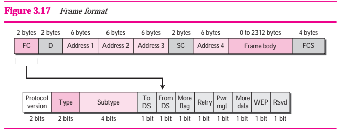
- Frame control (FC). The FC field is 2 bytes long and defines the type of frame and some control information. Table 3.5 describes the subfields. We will discuss each frame type later in this chapter.
- D. In all frame types except one, this field defines the duration of the transmission that is used to set the value of VAN. In one control frame, this defined the ID of the frame.
- Address. There are four address fieldd, each 6 bytes long. The meaning of each address field depends on the value of the To Ds and From DS subfields and will be discussed later.
- Swquence control. This field defines the sequence number of the frame to be used in flow control.
- Frame body. This field, which can be between 0 and 2312 bytes, contain information based on the type and the subtype defined in the FC field.
- FCS. The FCS field is 4 bytes long and contains a CRC-32 error detection sequnce.
Table 3.5 Subfield in FC field
| Filed | Explanation |
| Version | Current version is 0 |
| Type | Type of information: management (00), control (01), or data (10) |
| Subtype | Subtype of each type (see Table 3.6 ) |
| To DS | Defined later |
| From DS | Defined later |
| More flag | When set to 1, means more fragments |
| Retry | When set to 1, means retransmitted frame |
| Pwr mgt | When set to 1, means station is power managment mode |
| More data | When set to 1, means station has more data to send |
| WEP | Wired equivalent privacy (encryption implemented) |
| Rsvd |
Reserved |
Frame Type
A wireless LAN defined by IEEE 802.11 has three categories of frames: management frame, control frame, and data frames.
Management Frames Management frames are used for the initial communication between stations and access points.
Control Frames Control frames are used for accessing the channel and acknowledging frames Figure 3.18 shows the format.
Figure 3.18 Control frames
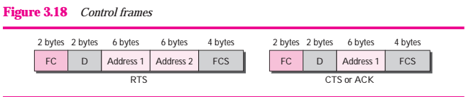
For control frames the value of the type field is 01; the values of the subtype fields for frames we have discussed are shows in Table 3.6.
Table 3.6 values of subfields in control frames
| subtype | Meaning |
| 1011 | Request to send (RTS) |
| 1100 | Clear to send (CTS) |
| 1101 | Achnowledgment (ACK) |
Data Frames
Data frames are used for carrying data and control information.
Addring Mechanism
The IEEE 802.11 addressing mechanism specifies four cases, defined by the value of the two flags in the FC field. To DS and From DS. Each flag can either 0 or , resulting in four different situations. The interpretation of the four addresses (address 1 to address 4) in the MAC frame depends on the value of these flags , as shown in Table 3.7.
Table 3.7 Addresses
| To DS | From DS | Address 1 | Address 2 | Address 3 | Address 4 |
| 0 | 0 | Destination | Source | BSS ID | N/A |
| 0 | 1 | Destination | Sending AP | Soure | N/A |
| 1 | 0 | Receiving AP | Source | Destination | N/A |
| 1 | 1 | Receiving AP | Sending AP | Destination | Source |
Note that address 1 is always the address of the next device. Address 2 is always the address of the previous device. Address 3 is the address of the final destination station if it is not defined by address1. Address 4 is the address of the original source station if it is not the same as address2.
Hidden and Exposed Station Problems
We referred to hidden and exposed station problems in the previous section. It is time now to discuss these problems and their effects.
Hidden station Problem
Figure 3.19 shows an example of the hidden station problem. Station B has a transmission range shown by the left oval (sphere in space); a transmission range shown by the right oval (sphere in space); every station located in this range can hear any signal transmitted by C. Station C is outside the transmission range of B; likewise, station B is outside the transmission range of C. Station A, however, is in the area covered by both B and C; it can hear any signal transmitted by B or C.
Figure 3.19 Hidden station problem
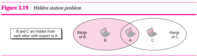
Assume that station B is sending data to station A. In the middle of this transmission, station C also has data to send to station A. However, station C is out of B's range and transmission from B cannot reach C. Therefore C thinks the medium is free. Station C sends its data to A, which results in a collision at A because this station is receiving data from both B and C. In this case, we say that stations B and C are hidden from each other with respect to A. Hidden stations can reduce the capacity of the network because of the possibility of collision.
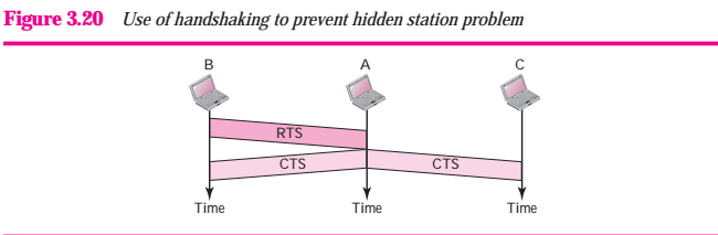
The solution to the hidden station problem is the use of the handshake frames (RTS and CTS) that we discussed earlier. Figure 3.20 shows that the RTS message from B reaches A, but not C. However, because both B and C are within the range of A, the CTS message, which contains the duration of data transmission from B to A reaches C. Station C knows that some hidden station is using the channel and refrains from transmitting until that duration is over
The CTS frame in CSMA/CA handshake can prevent collision from a hidden station
Figure 3.20 Use of handshaking to prevent hidden station problem
Exposed Station Problem
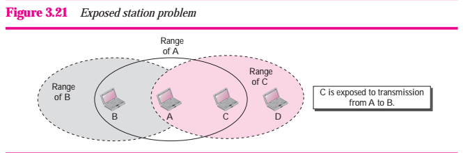
Now consider a situation that is the inverse of the previous one; the exposed station problem. In this problem a station refraints from using a channel when it is, in fact, available. In Figure 3.21, station A is transmitting to station B. Station C has some data to send to send to station D, which can be sent without interfering with the transmission from A to B. However, station C is exposed to transmissoin from A; it hears what A is sending and thus refrains from sending. In other words, C is too conservative and wastes the capacity of the channel.
Figure 3.21 Exposed station problem
The handshaking messages RTS and CTS cannot help in this case, despite what we might think. Figure 3.22 shows the situation
Staion C hears the RTS from A, but does not hear the CTS from B. Station C, after hearing the RTS from A, can wait for a time so that the CTS from B reaches A; it then sends an RTS to D to show that it needs to communicate with D. Both stations B and A may hear this RTS, but station A is in the sending state, not the receiving state. Station B, however, responds with a CTS. The problem is here. If station A has started sending its data, station C cannot hear the CTS from station D because of the collision; it cannot send its data to D. It remains exposed until A finishes sending its data.
Figure 3.22 Use of handshaking in exposed station problem

Bluetooth
Bluetooth is wireless LAN technology designed to connect devices of different functions such as telephones, notebooks, computers (desktop and laptop), cameras, printers , coffee makers, and so on. A Bluetooth LAN is an ad hoc network, which means that the network is formed spontaneously; the devices, sometimes called gadgets, find each other and make a network called a piconet. A Bluetooth LAN can even be connected to the Internet if one of the gadgets has this capability. A Bluthtooth LAN, by nature, can not be large. If there are many gadgets that try to connect, there is chaos.
Bluetooth technology has several applications. Peripheral devices such as a wireless mouse or keyboard can communicate with the computer through this technology. Monitoring devices can communicate with sensor devices in a small health care center. Home security devices can use this technology to connect different sensors to the main security controller. Conference attendees can synchronize their laptop computers at a conference.
Bluetooth was originally started as a project by the Ericsson Company. It is named for Harald Blaatand, the king of Denmark(940-981) who united Denmark and Norway. Blaatand translates to Bluetooth in English.
Today, Bluetooth technology is the implementation of a protocol defined by the IEEE 802.15 standard. The standard defines a wireless personal area network(PAN) operable in an area the size o a room or a hall.
Architecture
Bluetooth defines two types of networks: piconet and scatternet.
Piconets
A Bluetooth network is called a piconet, or a small net. A piconet can have up to eight stations, one of which is called the primary; the rest are called secondaries. All the secondary stations synchronize their clocks and hopping sequence with the primary. Note that a piconet can have only one primary station. The communicatoin between the primary and the secondary can be one-to-one or one-to-many. Figure 3.23 show a piconet.
Figure 3.23 Piconet
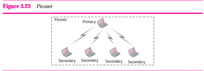
Although a piconet can have a maximum of seven secondaries, an additional eight secondaries can be in the parked state. A secondary in a parked state is synchronized with the primary, but can not take part in communication until it is moved from the parked state. Because only eight stations can be active in a piconet, activating a station from the parked state means that an active station must go to the parked state.
Scatternet
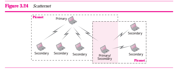
Piconet can be combined to form what is called a scatternet. A secondary station in one piconet can be the primary in another piconet. This station can receive messages from the primary in the first piconet (as a secondary) and, acting as a primary, deliver them to secondaries in the second piconet. A station can be a member of two picnets. Figure 3.24 illustrates a scatternet
Figure 3.24 Scatternet
Bluetooth Devices
A Bluetooth devices has a built-in short-range radio transmitter. The current data rate is 1 Mbps with a 2.4-GHZ bandwidth. This means that there is a possibility of interference between the IEEE 802.11b wireless LANs and bluetooth LANs
Frame Format
A frame in the baseband layer can be one of three types: one-slot, three-slot, or five-slot. A slot, as we said before, is 625μs. However, in a one-slot frame exchange, 259 μs is needed for hopping and control mechanisms. This means that a one-slot frame can last 625-259, or 366 μs , with a 1-MHz bandwidth and 1 bit / Hz, the size of one-slot frame is 366 bits.
A three-slot frame occupies three slots. However, since 259 μs is used for hopping, the length of the frame is 3×625 -259 = 1616 μs or 1616 bit. A device that uses a three-slot frame remain at the same hop (at the same carrier frequency) for three slots. Even through only one hop number is used, three hop numbers are consumed. That means the hop number for each frame is equal to the first slot of the frame. A five-slot frame also uses 259 bits for hopping, which means that the length of the frame is 5×625-259=1866 bit. Figure 3.25 shows the format of the three frame types.
Figure 3.25 Frame format types
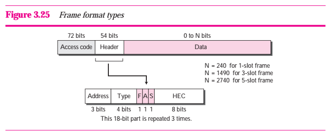
The following describes each field:
- Access code This 72-bit field normally contains synchronization bits and the identifier of the primary to distinguish the frame of one piconet from another.
- Header. This 54-bit field is a repeated 18-bit parttern has the following subfields:
- Address. The 3-bit address subfild can define up to seven secondaries (1 to 7). If the address is zero, it is used for broadcast communication from the primary to all secondaries.
- Type. The 4-bit type subfield defines the type of data coming from the upper layers. We discuss these types later.
- F. This 1-bit subfield is for flow control. When set (1), it indicates that the device is unable to receive more frame (buffer is full ).
- A. This 1-bit subfield is for acknowledgment. Bluthtooth uses stop-and-wait ARQ; 1 bit is sufficient for acknowledgment.
- S This 1-bit subfficient for sequence numbering.
- HEC. The 8-bit header error correction subfield is a checksum to detect errors in each 18-bit header section
The header has three identical 18-bit section. The receiver compares these three sections, bit by bit. If each of the corresponding bit is the same, the bit is accepted; if not, the majority opinion rules. This is a form of forward error correction (for the header only). This double error control is needed because the nature of the communication, via air, is very noisy. Note that there is no retransmission in this sublayer.
- Data This subfield can be 0 to 2740 bits long. It contains data or control information coming from the upper layers.
- The sending station, after sending that the medium is idel, sending a special small frame called request and send (RTS). In this message, the sender defines the total time it needs the medium.
- The receiver acknowledges the request (broadcast to all stations) by all sending a small packet called clear to send (CTS).
- The sender sends the data frame.
- The receiver acknowledges the receipt of data.